Optical signal quality monitor for a high-bit rate signal

a high-bit rate optical signal and optical signal technology, applied in the field of optical signal quality monitors, can solve the problems of difficult analysis of signals, complicated and expensive devices of sampling oscilloscopes, and may not be satisfactory to such high-bit rate optical signals, and achieve the effect of confirming appropriately the quality of even signals

Inactive Publication Date: 2012-02-21
OKI ELECTRIC IND CO LTD
View PDF31 Cites 7 Cited by
  • Summary
  • Abstract
  • Description
  • Claims
  • Application Information

AI Technical Summary

Benefits of technology

[0011]It is therefore an object of the present invention to provide an optical signal quality monitoring device that may confirm appropriately the quality of a high-bit rate optical signal.
[0013]In accordance with the present invention, it is therefore possible to confirm appropriately the quality of even the high-bit rate optical signal.

Problems solved by technology

Generally, the sampling oscilloscope is however a complicated and expensive device.
However, the monitoring method of the optical waveform taught by the above-mentioned Japanese '597 patent publication is subject to a difficulty that the higher bit rate of the optical signal to be observed the fewer sampling points, thus rendering it difficult to analyze the signal.
However, the methods taught by the above-mentioned Japanese '597 patent publication and U. K. Lize, et al., may not be satisfactory to such a high-bit rate optical signal.

Method used


Image

  • Optical signal quality monitor for a high-bit rate signal
  • Optical signal quality monitor for a high-bit rate signal
  • Optical signal quality monitor for a high-bit rate signal

Examples


first embodiment

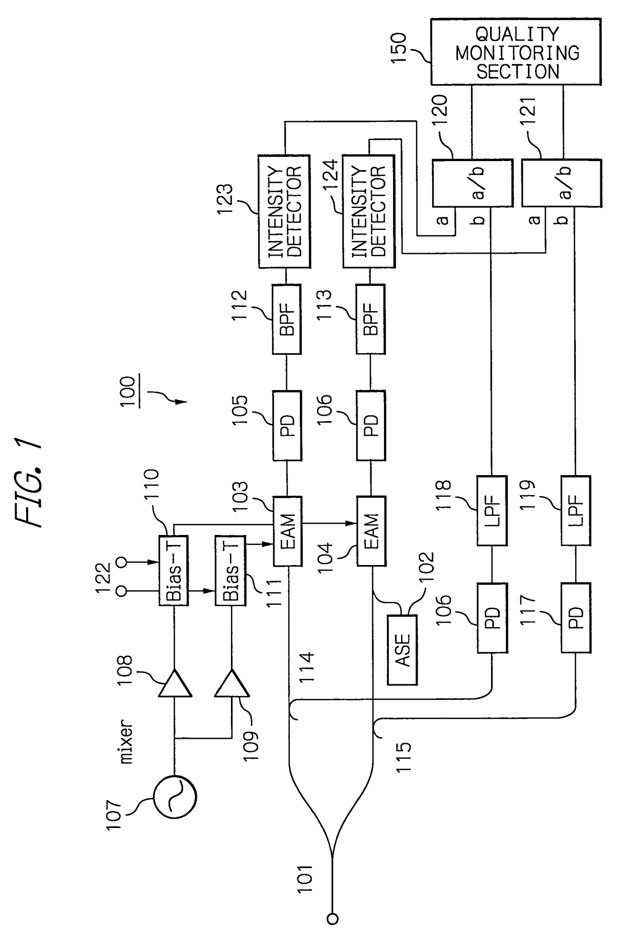
[0029]With reference to the accompanying drawings, illustrative embodiments of an optical signal quality monitor according to the present invention will be described below. First, reference is made to FIG. 1, which is a schematic block diagram showing an optical signal quality monitor 100. As shown in the figure, the optical signal quality monitor 100 includes constituent elements dealing with an optical signal and ones dealing with an electrical signal as well as a quality monitoring section 150.

[0030]The elements dealing with an optical signal are an optical splitter 101, an amplified spontaneous emission (ASE) generator 102, two electro-absorption (EA) modulators 103 and 104, four photo diodes (PD) 105, 106, 116 and 117, and two optical distributors 114 and 115, which are interconnected as illustrated. In the figure, optical connections are depicted with thick lines. The elements dealing with an electrical signal are a local oscillator 107, two drivers 108 and 109, two bias-Ts 11...

second embodiment

[0067]With reference to FIG. 7, a description will be given on why the optical band-pass filter 102A is used in the optical signal quality monitor 100A in the The graph shown in FIG. 7 plots the division signal a / b (Power decrease) from the divider 121 in the second line including the optical band-pass filter 102A with respect to the optical signal-to-noise ratio (OSNR) of the input optical signal to show a characteristic curve of the signal a / b.

[0068]As seen in FIG. 7, when using the optical band-pass filter 102A to receive the signal of 3 dB and then pass the frequency of band width Δf therethrough, it is possible to provide different intensity ratios a / b for the same OSNR depending on the band width. In other words, by suitably selecting the band width Δf of the optical band-pass filter 102A in inputting the 3 dB signal, it is possible to accurately detect the OSNR that could not be accurately detected only using the division signal a / b from the divider 120 in the first line, by...

third embodiment

[0072]With reference to FIG. 9, the primary polarization mode dispersion (PMD) is generally expressed by a differential group delay (DGD) generated between a given xi (ξ) axis component and another psi (ψ) axis component perpendicular to the ξ axis in the optical signal received from an optical fiber 204. the waveform distortion due to the DGD may be detected. As shown in FIG. 9, the input light has a delay difference caused by the DGD between the given ξ axis component and the other ψ axis component perpendicular to the ξ axis.

[0073]The polarizer 201 is adopted to polarize the input optical signal and to provide the resultant polarized signal to the monitoring device 203. The polarizer 201 rotates in response to a sinusoidal wave signal at a low frequency (here 10 Hz) generated by the oscillator 202. When the polarization axis of the polarizer 201 is parallel with the ξ axis or the ψ axis, the monitoring device 203 detects the same pulse shape as the transmitted waveform.

[0074]In ...


PUM


Abstract

An optical signal quality monitor includes a splitter splitting an input optical signal into two signals; a low-frequency converter converting one split optical signal to a low frequency signal by modulating the optical signal with a frequency offset signal; and an intensity ratio calculator calculating an intensity ratio between the low frequency signal and the other split optical signal, thereby appropriately confirming the quality of a high-bit rate optical signal. The monitor includes plural processing lines, each line including the splitter, the low-frequency converter, and the intensity ratio calculator. At least one line includes an optical noise superimposer superimposing optical noise on the one split signal before inputted to the converter or an optical band-pass filter transmitting the one split signal before inputted to the converter. The monitor includes a polarization state changer changing the polarization state of the input signal before inputted to the splitter.

Description

BACKGROUND OF THE INVENTION[0001]1. Field of the Invention[0002]The present invention relates to an optical signal quality monitor for monitoring, for example, a signal-to-noise ratio, polarization mode dispersion or the like of an optical signal in an optical transmission system.[0003]2. Description of the Background Art[0004]When investigating the quality or deterioration factor of a transmitted signal, an estimate of the quality or factor may require the waveform of the signal to be monitored.[0005]The waveform of an optical signal may be monitored by using devices such as a sampling oscilloscope. Generally, the sampling oscilloscope is however a complicated and expensive device. As opposed to such a device, there is also a proposal for monitoring the quality of an optical signal without using the sampling oscilloscope.[0006]Japanese patent laid-open publication No. 2005-151597 discloses an optical signal quality monitor that samples an optical signal to be measured having a pred...

Claims


Application Information

Patent Timeline
Patent Type & Authority Patents(United States)
IPC IPC(8): H04B10/08G02B6/00G01B9/02H04J14/02H04B10/556H04B10/07H04B10/2507H04B10/54
CPCH04B10/07953
Inventor KAGAWA, MASATOSHI
Owner OKI ELECTRIC IND CO LTD
Why Eureka
Try Eureka