Apparatus for connecting bars

Inactive Publication Date: 2010-12-02
KIM SEO JI +2
View PDF8 Cites 15 Cited by
  • Summary
  • Abstract
  • Description
  • Claims
  • Application Information

AI Technical Summary

Benefits of technology

[0020]According to the apparatus for connecting bars of the present invention, the tensile and yield strength thereof is increased even its smaller size since the stopper is designed in two steps and the contacting area between a stopper and the bars and the contacting area between the stopper and its body are increased

Problems solved by technology

Therefore, the joint is limited to be further smaller, which in

Method used


Image

  • Apparatus for connecting bars
  • Apparatus for connecting bars
  • Apparatus for connecting bars

Examples


Example

[0029]Hereinafter, the apparatus for connecting bars according to preferred embodiment of the present invention will be described in detail with reference to the accompanying drawings.

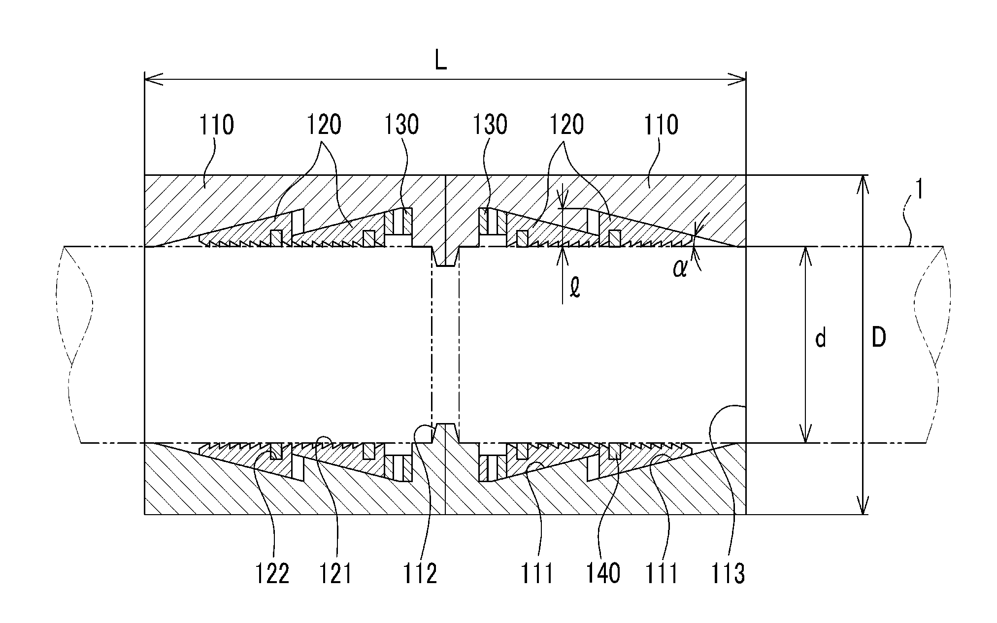
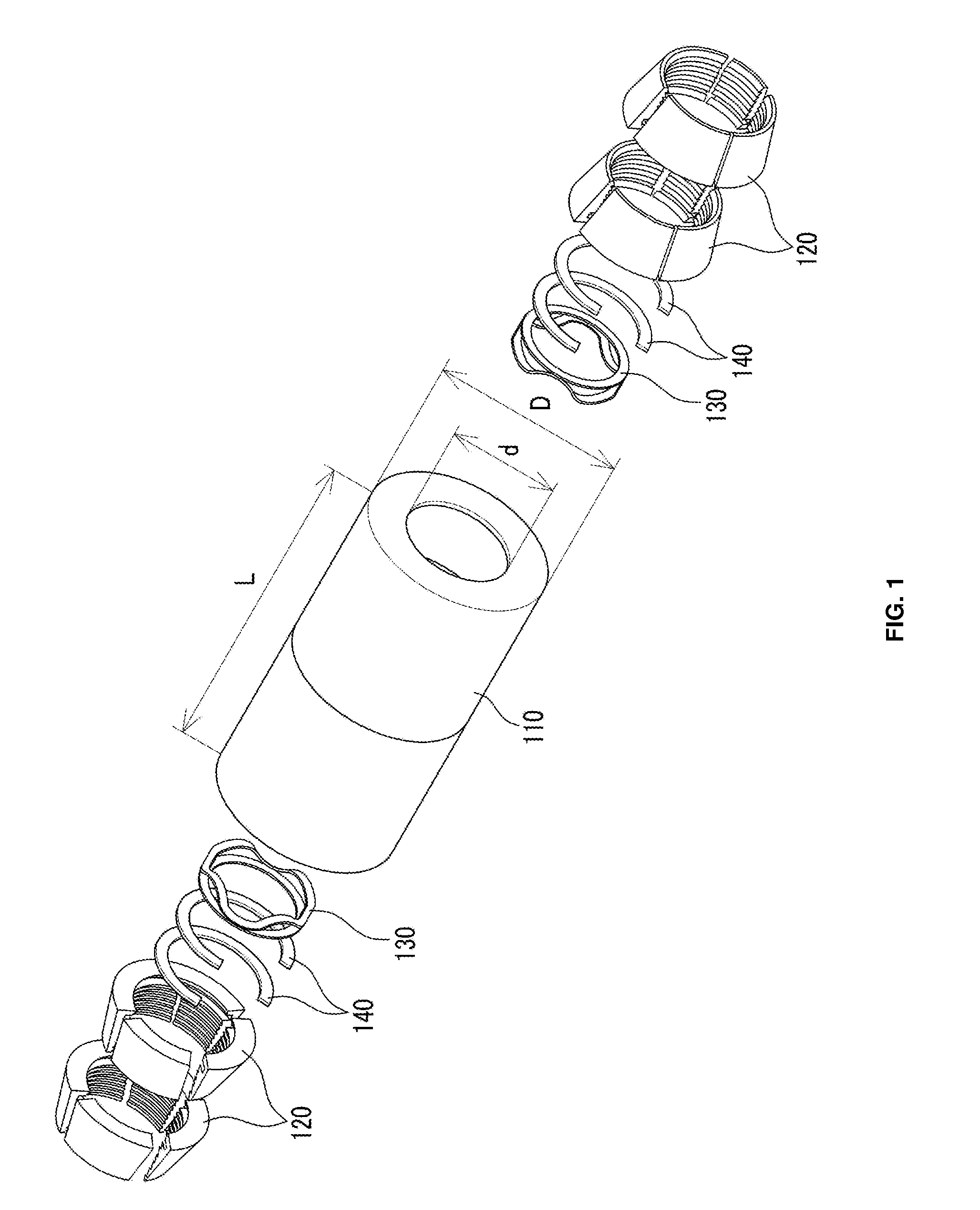
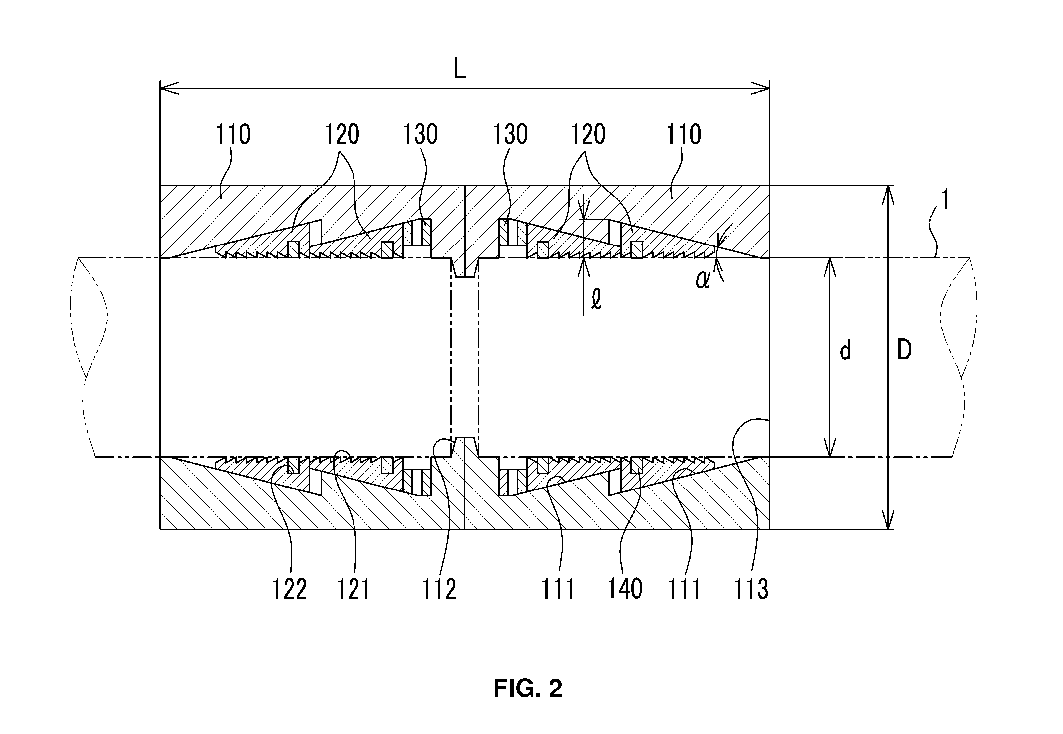
[0030]The apparatus for connecting bars according to a preferred embodiment of the present invention is described with reference to FIGS. 1, 2 and 3. FIG. 1 is a broken perspective view schematically illustrating the apparatus for connecting bars according to a preferred embodiment of the present invention, FIG. 2 is a cross-sectional view schematically illustrating the apparatus for connecting bars in which the stoppers are mounted in two steps, and FIG. 3 is a cross-sectional view schematically illustrating the apparatus for connecting bars in which the stoppers are mounted in three steps.

[0031]As shown in FIGS. 1, 2 and 3, the apparatus 100 for connecting bars according to this embodiment comprises a pair of bodies 110, a plurality of stoppers 120, a spring 130 and an elastic ring 140.

[0032]The pair...


PUM


Abstract

The apparatus 100 for connecting bars according to the present invention comprises a pair of bodies 100 for receiving the bars 1, the pair of bodies having cylindrical shape which faces from each other; a plurality of stoppers 120 for firmly holding the bars 1, the plurality of stoppers 120 provided in the pair of bodies in two steps or several steps; a spring 130 for elastically longitudinally supporting the pair of bodies 110, the spring 130 provided in the bottom surface of the plurality of stoppers 120; and an elastic ring 140 for elastically supporting the plurality of stoppers 120 in the radial direction of the pair of bodies, the elastic ring 140 provided on the inner peripheral surface of the plurality of stoppers 120.

Description

REFERENCE TO RELATED APPLICATIONS[0001]This application is a continuation of PCT international application Ser. No. PCT / KR2010 / 000773 filed on Feb. 9, 2010, which designates the United States and claims priority of KR Application Serial No. 10-2009-0047868, filed May 30, 2009, the entire contents of which are incorporated herein by reference.FIELD OF THE INVENTION[0002]The present invention relates to an apparatus for connecting bars, and more particularly, to an apparatus for connecting bars enabling to easily and firmly connect two or more reinforcing rods or pipes.BACKGROUND OF THE INVENTION[0003]As one of apparatus for connecting bars such as reinforcing rods or pipes, there is “Joint for Pipes” of Korean Registered Utility Model No. 20-0347218.[0004]As shown in FIG. 6, the conventional joint for pipes has a couple of bodies 20.[0005]The couple of bodies 20 are arranged such that pipes 10 are respectively inserted into both entrances 26 thereof, and the entrances 26 are installe...

Claims


Application Information

Patent Timeline
IPC IPC(8): F16B7/00
CPCE04C5/165F16B7/0426Y10T403/5733
Inventor KIM, SEO JIKIM, YU SIECHOI, YOUNG SOOK
Owner KIM SEO JI
Why Eureka
Try Eureka