Hydraulic elevation apparatus and method

a technology of hydraulic equipment and hydraulic lift, which is applied in the direction of foundation engineering, construction, caissons, etc., can solve the problems of inefficient and relatively costly methods and devices used to lift rocks, insufficient space utilization, and insufficient cost of hoisting materials individually or by load in existing vertical shafts, etc., to achieve the effect of reducing labor intensity, reducing labor intensity, and reducing labor intensity

Inactive Publication Date: 2010-12-02
GUENTHER ROSS
View PDF34 Cites 3 Cited by
  • Summary
  • Abstract
  • Description
  • Claims
  • Application Information

AI Technical Summary

Benefits of technology

[0063]Viewed from a twenty-fourth vantage point, it is an object of the present invention to provide a method for transporting animate or inanimate objects employing flotation elevation, the steps including: (A) depositing a transport container into a first chamber of a multiple chamber framework internally disposed within at least one single shaft structure; (B) loading or unloading ...

Problems solved by technology

A persistent and formidable challenge in mining and related industries is implementing cost effective, efficient and reliable devices and methods for lifting objects either from beneath the earth's surface or to elevations above the earth's surface.
For instance, currently within the underground mining industry, demonstrably inefficient and relatively costly methods and devices are employed to lift rock and other objects from subsurface levels to above the earth's surface.
However, hoisting materials either individually or by load in existing vertical shafts is often inordinately space consuming, time consuming, costly, and consequently inefficient.
Vertical shaft hoisting generally requires an entire shaft compartment to lift a single load contained in a bucket or similar container, and additionally requires considerable time to lower the container back down the same shaft compartment to complete the hoisting cycle of a single container.
Moreover, vertical shaft hoist lifting devices and methods require the use of relatively expensive equipment, including hoists, wire rope, and corresponding mechanical parts, which are not only high maintenance, but also demand frequent replacement as a consequ...

Method used


Image

  • Hydraulic elevation apparatus and method
  • Hydraulic elevation apparatus and method
  • Hydraulic elevation apparatus and method

Examples


Embodiment Construction

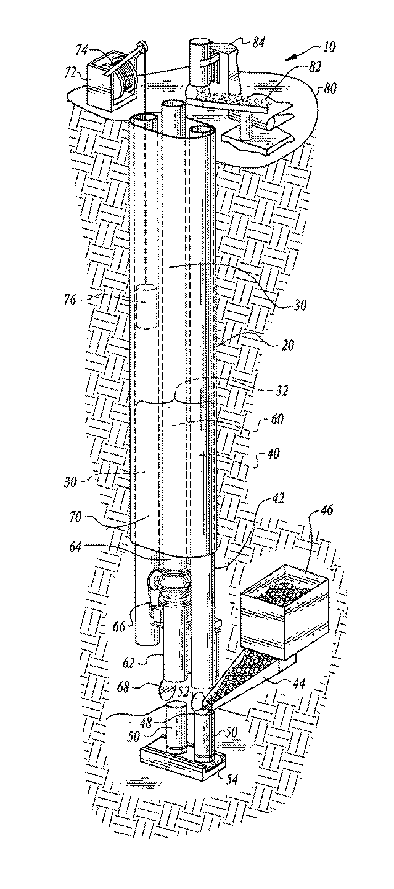
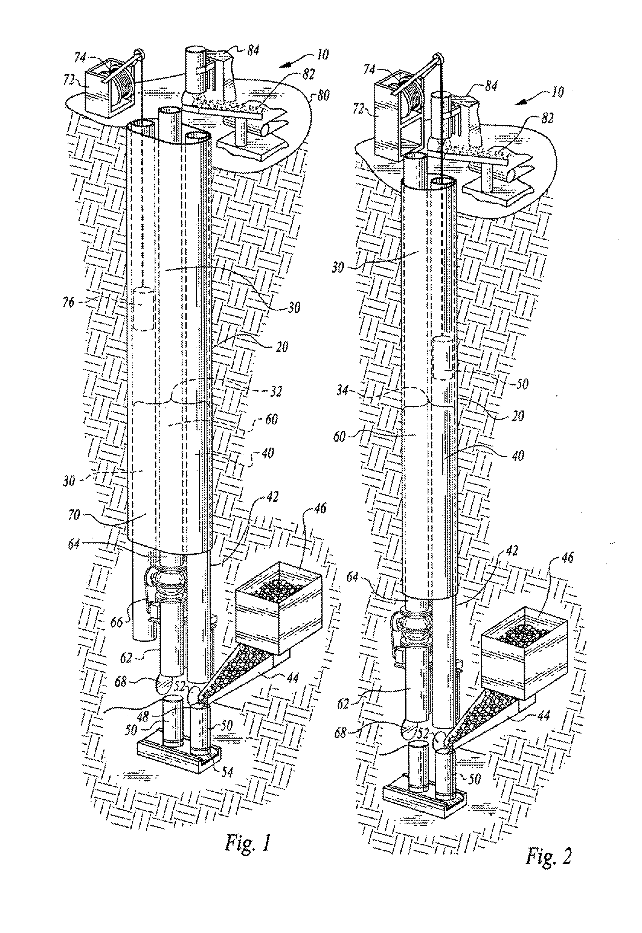
[0096]Elevation apparatus (10) of the present invention employs fluid to elevate animate or inanimate objects from beneath the earth's surface or to a point above the earth's surface within preferably at least one single shaft elevation structure (20), which may be positioned downward into the earth's interior, or positioned above the earth's surface. Shaft elevation structure (20) incorporates an internally disposed chamber framework (30) by which objects are transported within shaft elevation structure (20). Shaft elevation structure (20) is typically a single shaft structure, but may consist of multiple shaft structures incorporating chamber framework (30). Chamber framework (30) may be constructed within shaft elevation structure (20) by various shaft rehabilitation techniques, and may be incorporated into existing shaft structures. Chamber framework (30) may alternatively be constructed within newly drilled shaft structures.

[0097]FIGS. 1 and 2 depict preferred embodiments of el...


PUM


Abstract

The hydraulic transportation apparatus and method of the present invention incorporate a multiple chamber framework internally disposed preferably within at least one single shaft structure, which facilitates movement of object transport containers within the multiple chamber framework. Preferably, fluid elevation is employed to elevate and lower object transport containers and their contents within the multiple chamber framework. Each single shaft structure may be constructed from an existing rehabilitated shaft, or a newly drilled shaft. The present invention may be utilized in vertical or incline lifting environments, and an auxiliary hoist chamber may be incorporated into the multiple chamber framework for use as an alternative to, or in conjunction with, elevating objects by employing fluid elevation. The present invention may be employed in a variety of heavy lifting scenarios, including underground mining or in above ground lifting environments.

Description

CROSS REFERENCE TO RELATED APPLICATIONS[0001]This application is a Continuation-in-part of U.S. patent application Ser. No. 12 / 648,912, filed on Dec. 29, 2009, currently pending, which is a Divisional of U.S. patent application Ser. No. 11 / 437,973, now U.S. Pat. No. 7,661,910, the contents of both of which are incorporated herein by reference in their entireties.BACKGROUND OF THE INVENTION[0002]1. Field of the Invention[0003]The present invention generally relates to an apparatus and method for lifting objects by flotation from beneath the earth's surface or to elevations above the earth's surface within at least one single shaft structure. More specifically, the present invention provides an apparatus and method for conveying objects within at least one multiple chamber single shaft structure positioned beneath the earth's surface or above the earth's surface, and elevating and descending objects within the shaft structure by employing fluid buoyancy.[0004]2. Description of the Rel...

Claims


Application Information

Patent Timeline
IPC IPC(8): B65G51/00
CPCB65G51/04E21F13/00
Inventor GUENTHER, ROSS
Owner GUENTHER ROSS
Why Eureka
Try Eureka