Operative instrument
a technology of operative instruments and incision forceps, which is applied in the field of operative instruments, can solve the problems of insufficient coagulation of anatomy, long time-consuming and laborious, and achieve the effect of preventing early deterioration of the heat-generating body
- Summary
- Abstract
- Description
- Claims
- Application Information
AI Technical Summary
Benefits of technology
Problems solved by technology
Method used
Image
Examples
first embodiment
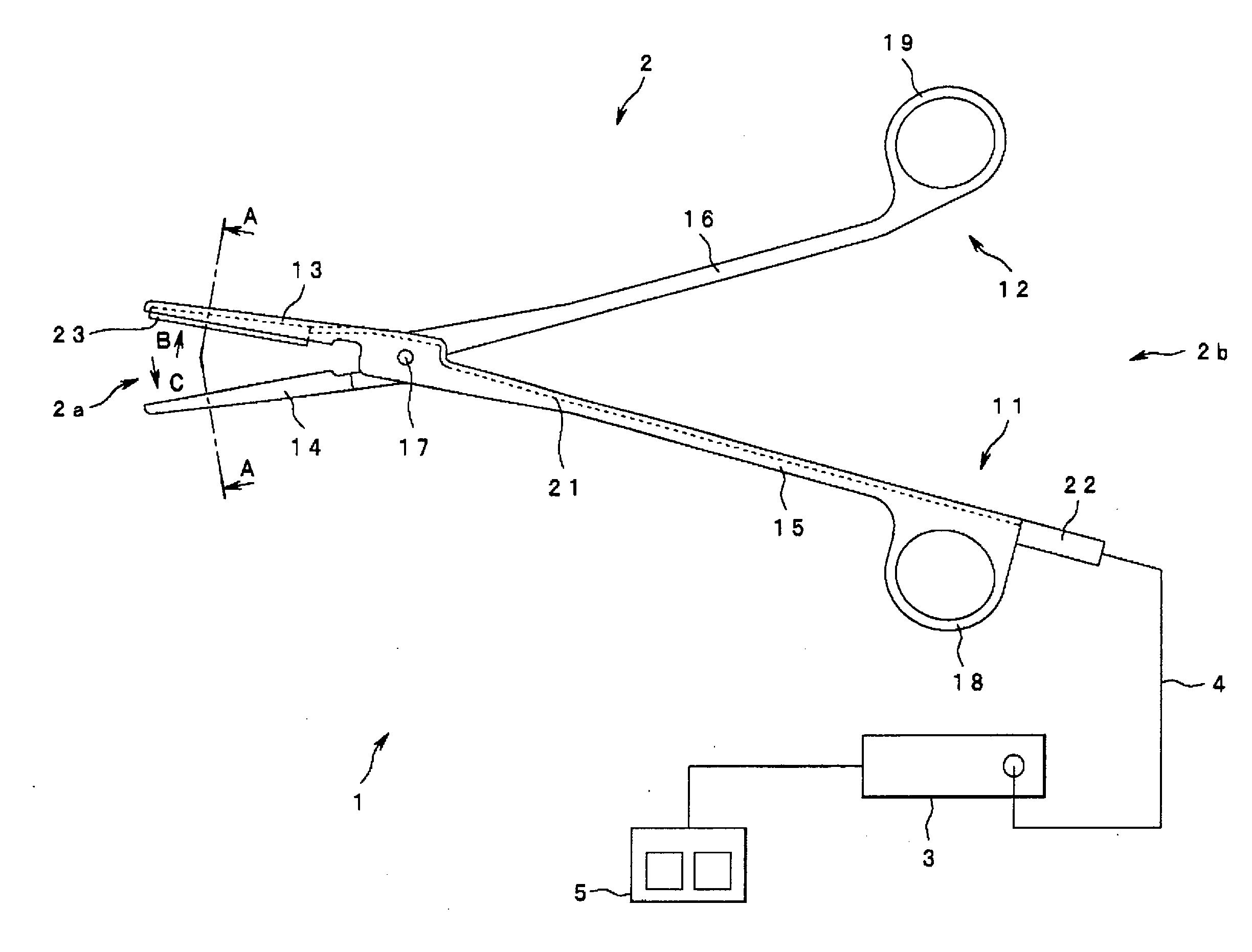
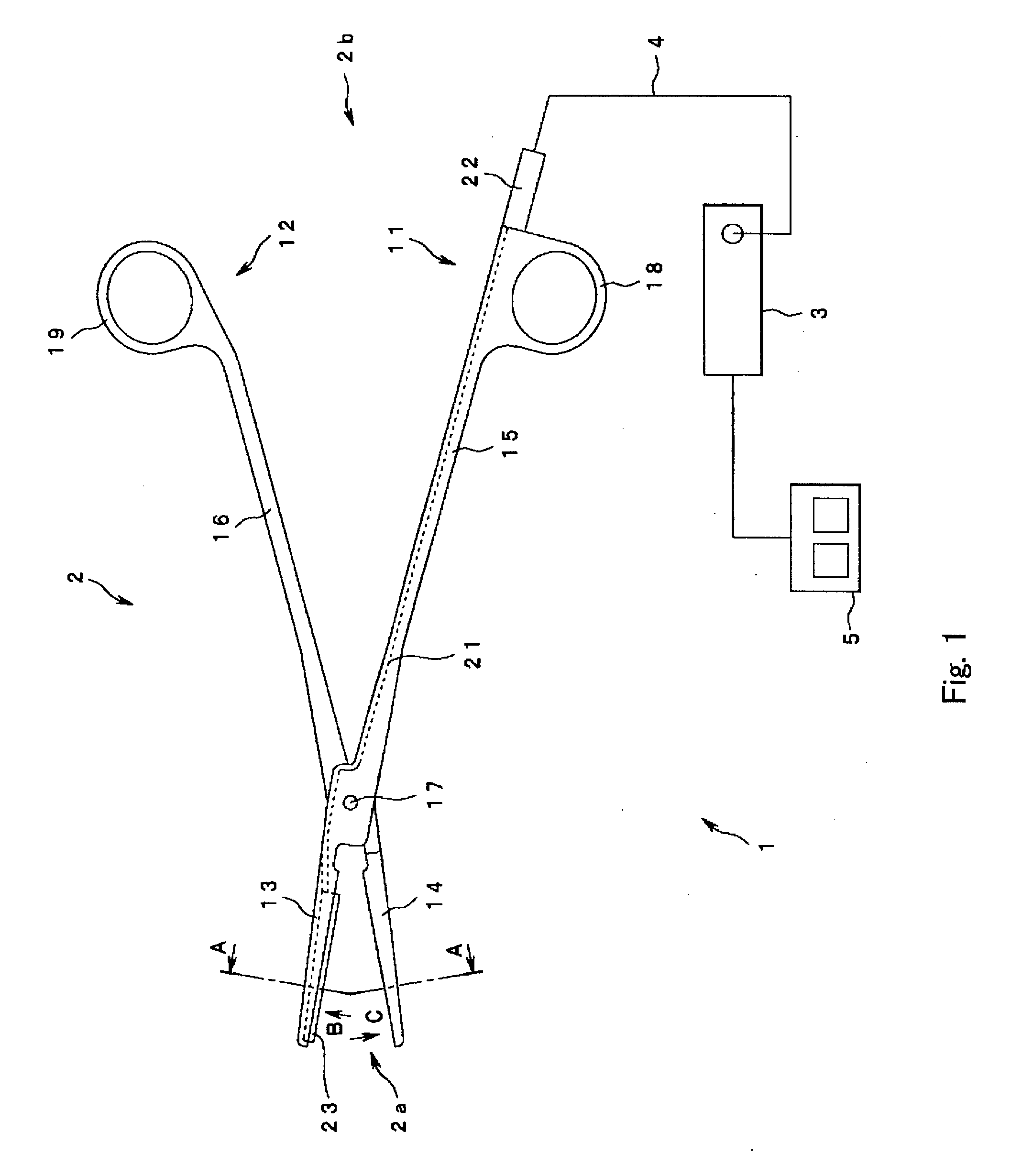
[0061]As shown in FIG. 1, an operative instrument 1 of the first embodiment includes forceps 2 that provide heat to an anatomy which they grip to effect coagulating and incising that anatomy. A power supply unit 3 that can be disconnectably connected to the forceps 2 outputs electric power of a power source (electric energy) to the forceps 2 to drive and control the same.
[0062]The forceps 2 are adapted in such a manner that a connector (not shown) provided at the rear end of a connecting cord 4 extending therefrom can be disconnectably connected to the power supply unit 3.
[0063]A foot switch 5 can be connected to the power supply unit 3. The operator can turn the power source to the forceps 20N and OFF by turning the foot switch 50N and OFF. A front panel of the power supply unit 3 is provided with a display device for displaying a current value or a voltage value of the power source supplied to the forceps 2 and an operating tab for entering various setting values on a panel input / ...
second embodiment
[0109]FIG. 17 to FIG. 20 is a graph of output control performed by the control circuit according to the invention. FIG. 17 is a graph of output voltage with respect to time; FIG. 18 is a graph of output current with respect to time; FIG. 19 is a graph of output electric power with respect to time; and FIG. 20 is a graph of electric resistance of the heat-generating body with respect to time.
[0110]Although constant voltage control is performed in the first embodiment, constant current control is performed in the second embodiment. Other structures are the same as the first embodiment and hence will not be described again, and the same structures are represented by the same reference numeral in description.
[0111]In other words, as shown in FIG. 17 to FIG. 20, the operative instrument 1 of the second embodiment is controlled in such a manner that the current I flowing in the heat-generating body 23 is kept constant (constant current control), and output is stopped when the heat-generat...
third embodiment
[0120]FIG. 21 to FIG. 24 are graphs of output control performed by a control circuit according to the invention. FIG. 21 is a graph showing output voltage with respect to time; FIG. 22 is a graph of output current with respect to time; FIG. 23 is a graph of output electric power with respect to time; and FIG. 24 is a graph of electric resistance of the heat-generating body with respect to time.
[0121]While constant voltage control is provided in the first embodiment, the third embodiment is based on constant electric power control. Since other structures are the same as in the first embodiment, description will not be made again and the same structures are represented by the same reference numerals in description.
[0122]In other words, in the operative instrument 1 according to the third embodiment, the electric power P supplied to the heat-generating body 23 is kept constant (constant electric power control), and output is stopped when the heat-generating body 23 reaches the preset u...
PUM
 Abstract
Description
Claims
Application Information
 - R&D
- Intellectual Property
- Life Sciences
- Materials
- Tech Scout
- Unparalleled Data Quality
- Higher Quality Content
- 60% Fewer Hallucinations
Browse by: Latest US Patents, China's latest patents, Technical Efficacy Thesaurus, Application Domain, Technology Topic, Popular Technical Reports.
© 2025 PatSnap. All rights reserved.Legal|Privacy policy|Modern Slavery Act Transparency Statement|Sitemap|About US| Contact US: help@patsnap.com


