Structural flange connection system and method

a technology of connecting system and flange, applied in the direction of mechanical equipment, building repairs, machines/engines, etc., can solve the problems of compromising clamping load, flange contact surfaces not being ideal plane, and more problems with wind turbine tower design

Active Publication Date: 2010-12-09
WORD III THOMAS NOTT +1
View PDF24 Cites 67 Cited by
  • Summary
  • Abstract
  • Description
  • Claims
  • Application Information

AI Technical Summary

Benefits of technology

[0031]The mechanical bond between the first structural flange and the second structural flange may be formed by fitting the series of protruding frusta located on the outer span of the face of the first structural flange in the series of mating detents located on the outer span of the face of the second structural flange and the series of protruding frusta located on the inner span of the face of the second structural flange in the series of mating detents located on the inner span of the face of the first structural flange, such that each of the protruding frustum located on the outer span of the face of the first structural flange is

Problems solved by technology

New and more efficient wind turbine generators are being developed that are larger and produce more energy, but also produce more problems with regard to wind turbine tower design that combat the operational forces prevalent in normal operations of the wind turbine.
However, this clamping load can be compromised in service by the fact that manufacturing tolerances can result in the flange contact surfaces not being ideally plane.
As the clamping load is now a smaller part of the overall load experienced by the bolt, and the fluctuating load is a larger portion of that load, there is a potential for metal fatigue to be generated within the bolt of the connection, leading to its eventual failure.
These forces that are inherent with normal wind tower turbine operations create the need for strict and costly maintenance procedures to ensure that the bolts at the flange joints are torqued to design specifications in order to maintain their design preload and re-establish any preload compromised due to a settling or deflection of the flange connection faces, and any damaged or failed due to metal fatigue are replaced in a timely manner.
As these small deformations occur and the flange connections settle, dimensional variations between the mating flange faces can compromise the preload of the bolted connection.
If the flange faces are distorted by the manufacturing process, then a mismatch can occur.
A potential for flange mismatch is generated by the nature of fabricating the tower sections.
When the

Method used


Image

  • Structural flange connection system and method
  • Structural flange connection system and method
  • Structural flange connection system and method

Examples


Embodiment Construction

[0044]The systems and methods discussed herein are merely illustrative of specific manners in which to make and use this invention and are not to be interpreted as limiting in scope.

[0045]While the systems and methods have been described with a certain degree of particularity, it is to be noted that many modifications may be made in the details of the construction and the arrangement of the structural and functional devices, components and / or steps without departing from the spirit and scope of this disclosure. It is understood that the systems and methods are not limited to the embodiments set forth herein for purposes of exemplification.

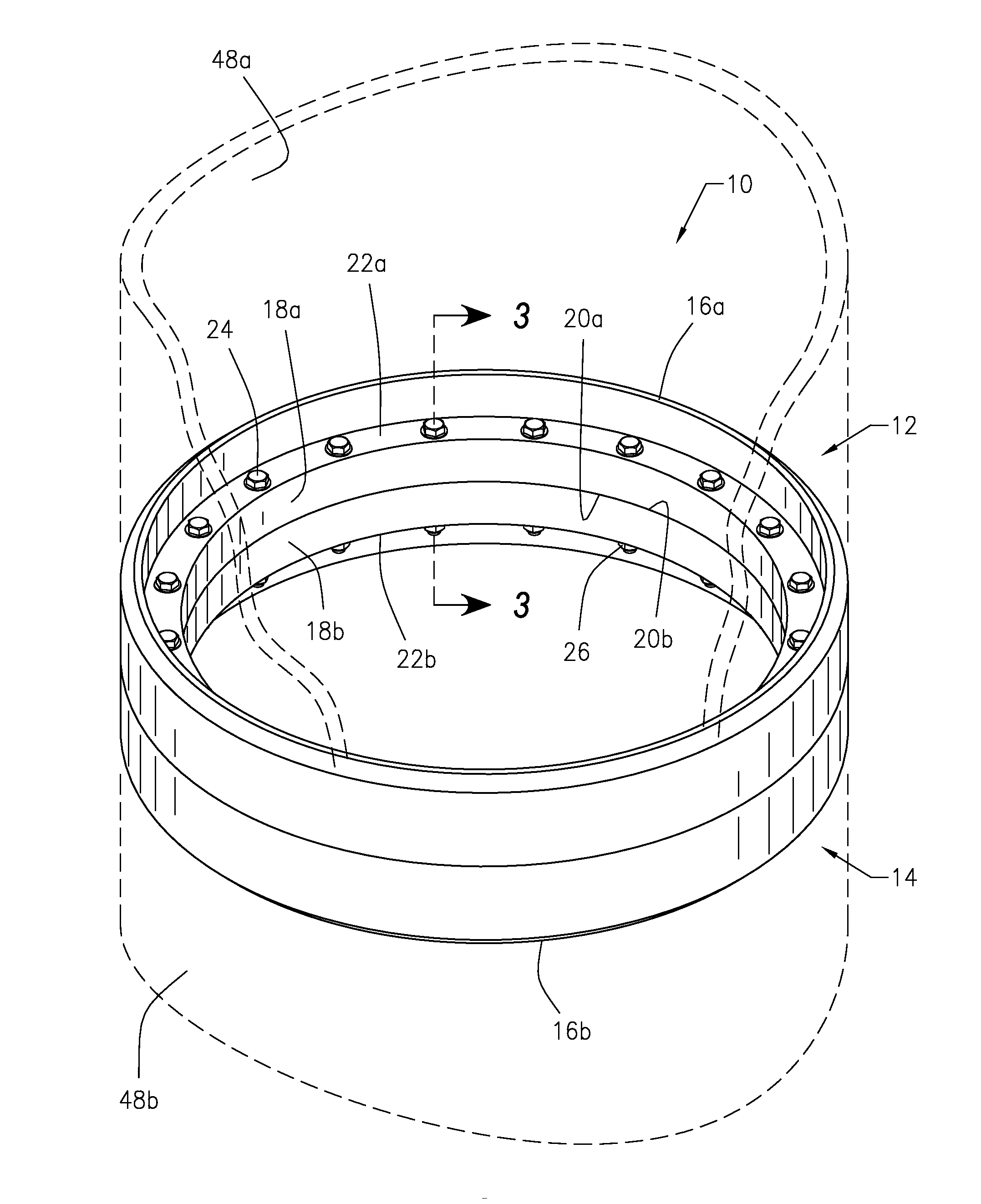
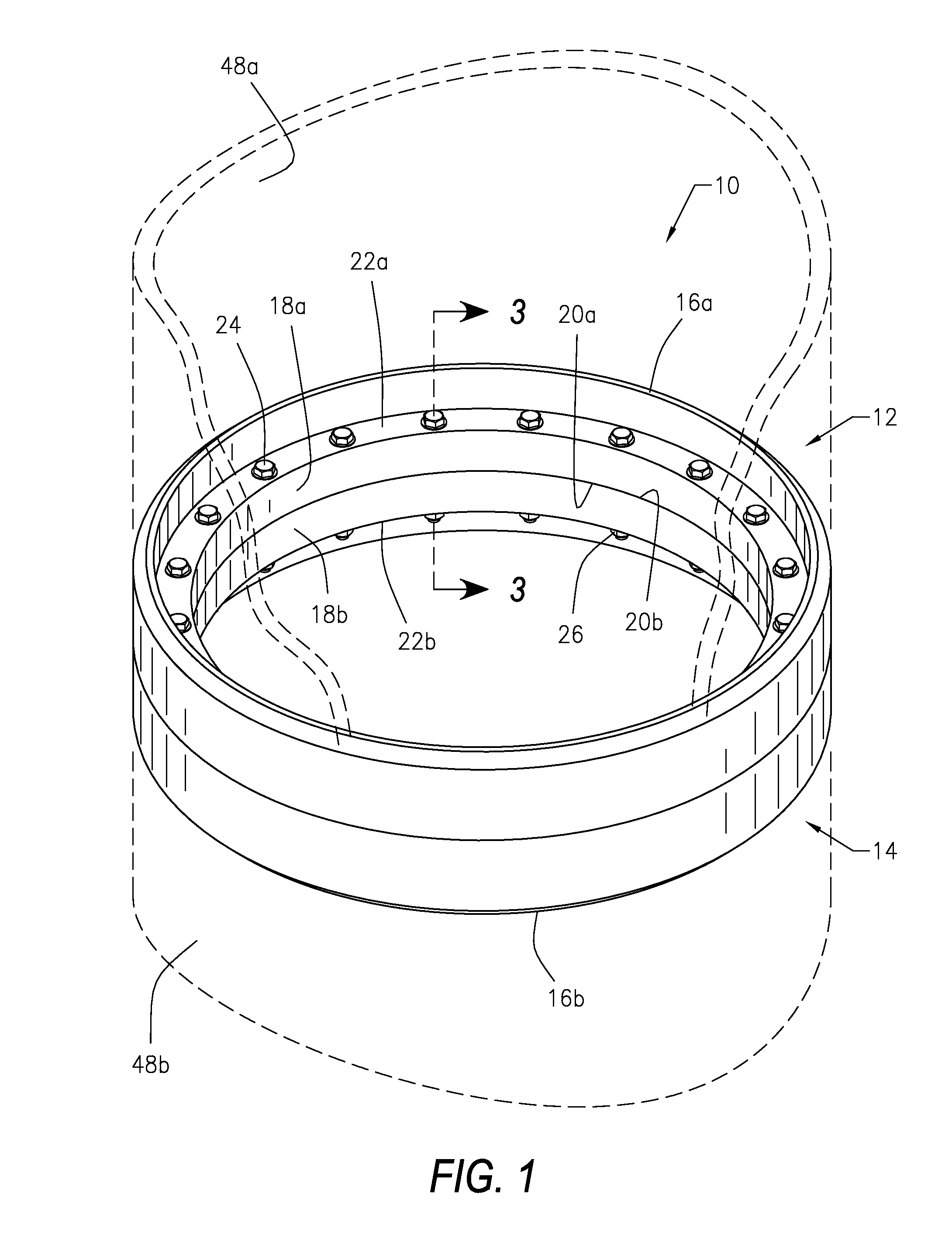
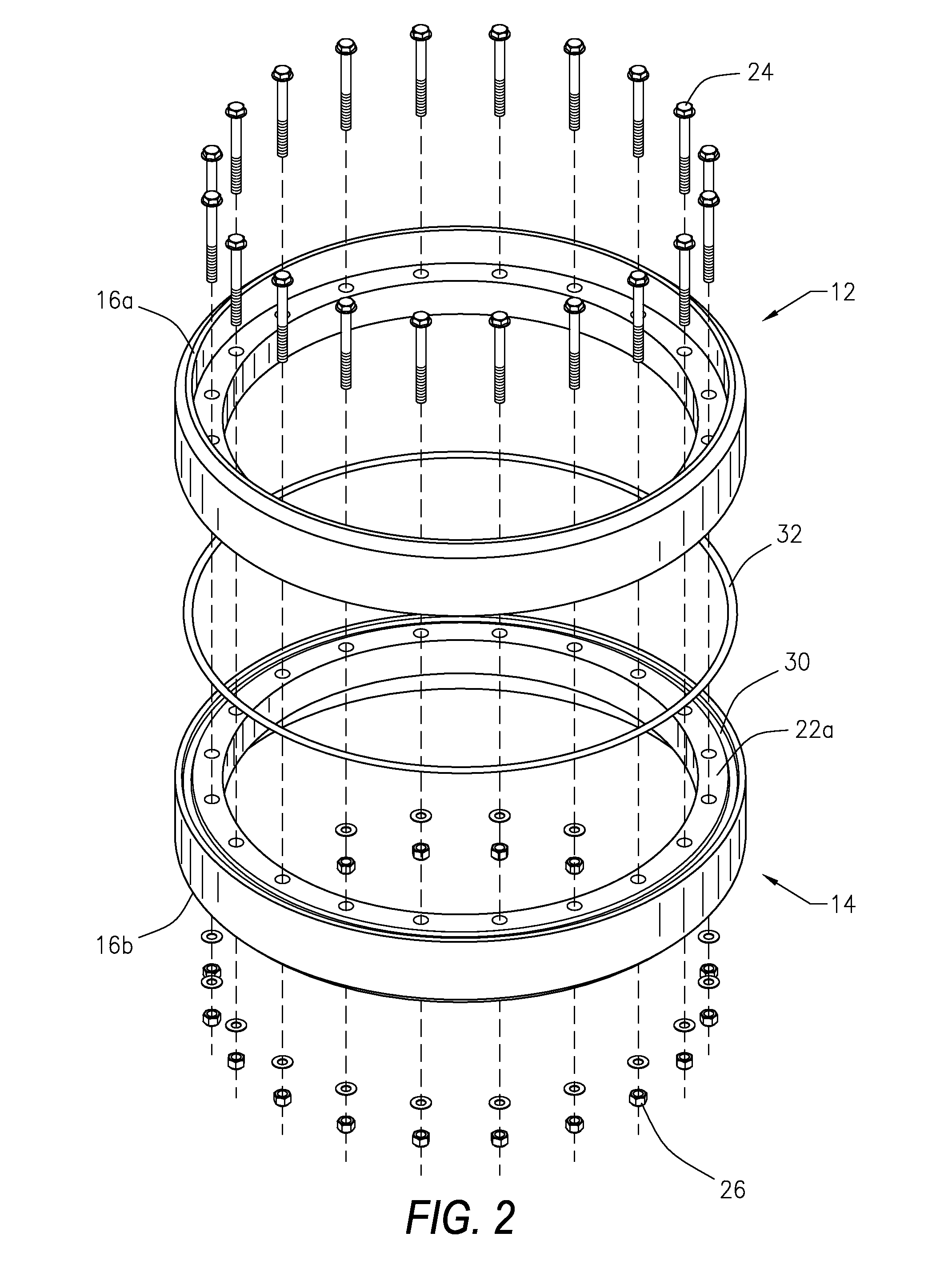
[0046]Referring to the figures of the drawings, wherein like numerals of reference designate like elements throughout the several views, and initially to FIG. 1, a structural flange connection system and method 10 utilizes structural flanges 12 and 14 having a mechanical bond that manages and assists the retention of bolt preloads and eliminates mo...


PUM


Abstract

A structural flange connection system and method that utilizes structural flanges having a standard bolted connection and a mechanical bond to effectively manage and assist the retention of bolt preloads and substantially eliminate movement between the flange faces due to a reduction in the need for friction load being generated by the bolt clamping force in the flange connection. The structural flanges of the structural flange connection system and method each include an outer rim and a flange lip having a face and a shoulder. The structural flange connection system and method may be utilized in the manufacture and installation of a wind turbine tower, which may be made up of one or more tower sections, and each tower section may terminate in structural flanges of the structural flange connection system and method. When properly aligned, the structural flanges may be bolted together. When each tower section is properly aligned and bolted, the mechanical bond of the structural flanges is also joined together. Such manufacture of the wind turbine tower may occur in the field during installation of the wind turbine tower.

Description

CROSS-REFERENCE TO RELATED APPLICATIONS[0001]This application claims priority to U.S. Provisional Application Ser. No. 61 / 185,238 filed Jun. 9, 2009, which is incorporated herein by reference.BACKGROUND OF THE INVENTION[0002]1. Field of the Invention[0003]This invention relates generally to a structural flange connection system and method, and more particularly to a structural flange connection system and method that utilizes structural flanges having a standard bolted connection and a mechanical bond effectively managing and assisting the retention of bolt preloads, and substantially eliminating movement between the flange faces, due to a reduction in the compromise of bolt preload due to flange face mismatch which can occur during the production of the flange connection joint.[0004]2. Description of the Related Art[0005]A great deal of interest is presently being shown in the development of alternative energy sources, particularly wind energy. New and more efficient wind turbine g...

Claims


Application Information

Patent Timeline
IPC IPC(8): E04H12/00E04B1/38
CPCE04H12/085F05B2230/604F05B2240/912F05B2260/301
Inventor WORD, III, THOMAS NOTTHARTMAN, JR., CECIL LEON
Owner WORD III THOMAS NOTT
Why Eureka
Try Eureka