Cylinder valve with thermal relief feature

a technology of cylinder valve and thermal relief, which is applied in the direction of functional valve types, container discharging methods, containers, etc., can solve the problems of unsatisfactory reactive gases, adversely affecting the test procedures discussed above, and the concentration of trace gases

Active Publication Date: 2010-12-09
CONTROL DEVICES
View PDF36 Cites 17 Cited by
  • Summary
  • Abstract
  • Description
  • Claims
  • Application Information

AI Technical Summary

Benefits of technology

[0005]In one embodiment, the present invention is directed to a cylinder valve with a thermal relief feature for use with a cylinder containing fluid under pressure. The cylinder valve comprises a valve body configured for releasable connection to the cylinder. The valve body has a front end, a back end, a flow passage extending through the valve body from the front end to the back end for fluid communication with an interior of the cylinder when the valve body is connected to the cylinder, and valve body surfaces which are exposed to fluid in the cylinder when the valve is connected to the cylinder. A valve in the flow passage is movable between open and closed positions. A vent passage is in the valve body and is separate from the flow passage for venting fluid under pressure from the cylinder. The cylinder valve further comprises a temperature relief insert in the vent passage. The insert comprises an insert body, a bore through the insert body, and a thermal relief material in the bore blocking flow through the bore until a predetermined venting temperature is reached whereupon the thermal relief material is adapted to change from a solid state to a more liquid state to allow venting of the cylinder through the bore and the vent passage. The valve body does not contain brass and the insert body comprises brass covered by a metal plating not containing brass.

Problems solved by technology

Since brass contains a significant amount of copper, it is undesirable to have such reactive gases come into contact with the brass in the relief valve 1.
Any such contact can potentially change the concentration of the trace gases in the cylinder, which will adversely affect the test procedures discussed above.

Method used


Image

  • Cylinder valve with thermal relief feature
  • Cylinder valve with thermal relief feature
  • Cylinder valve with thermal relief feature

Examples


Embodiment Construction

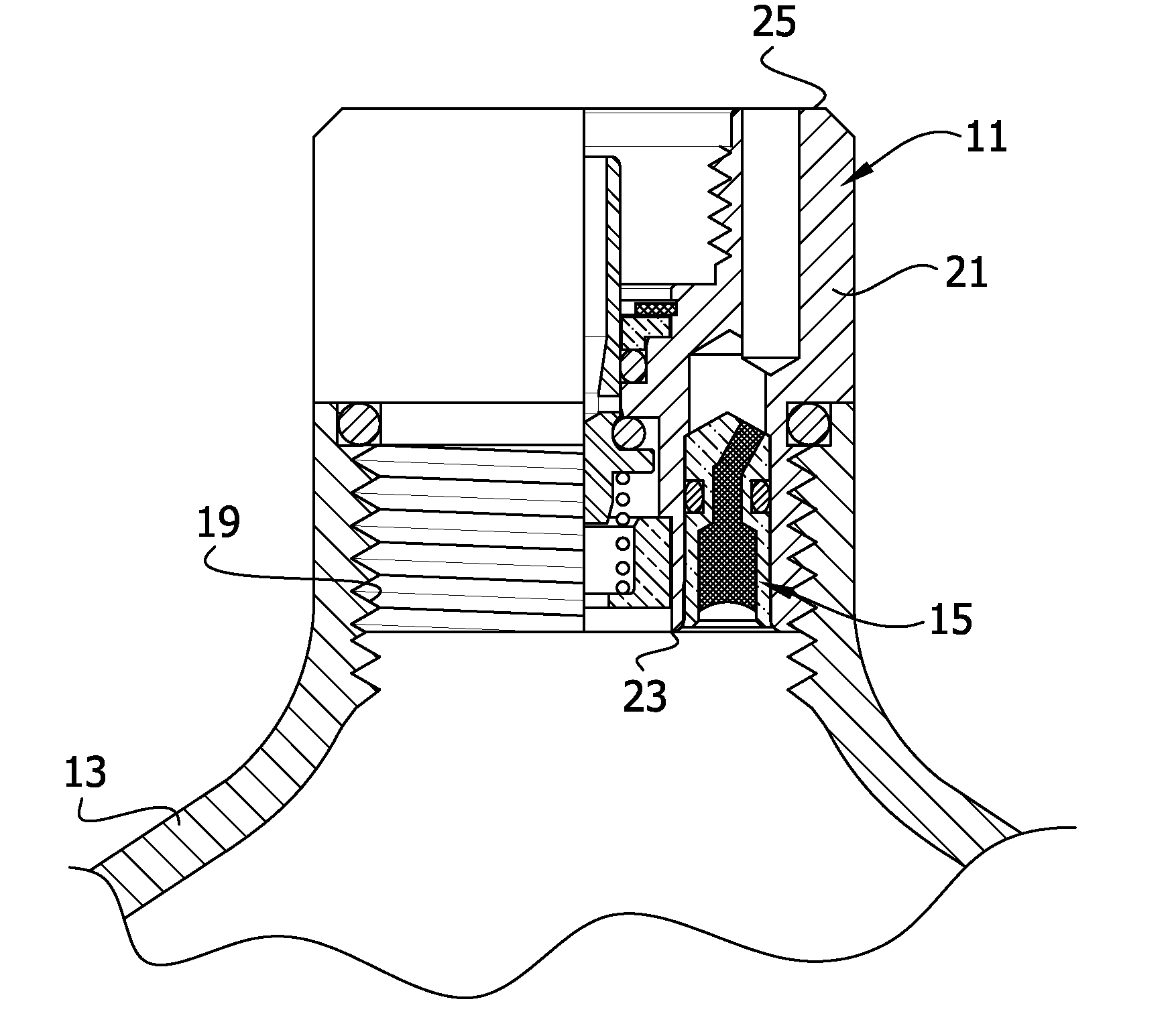
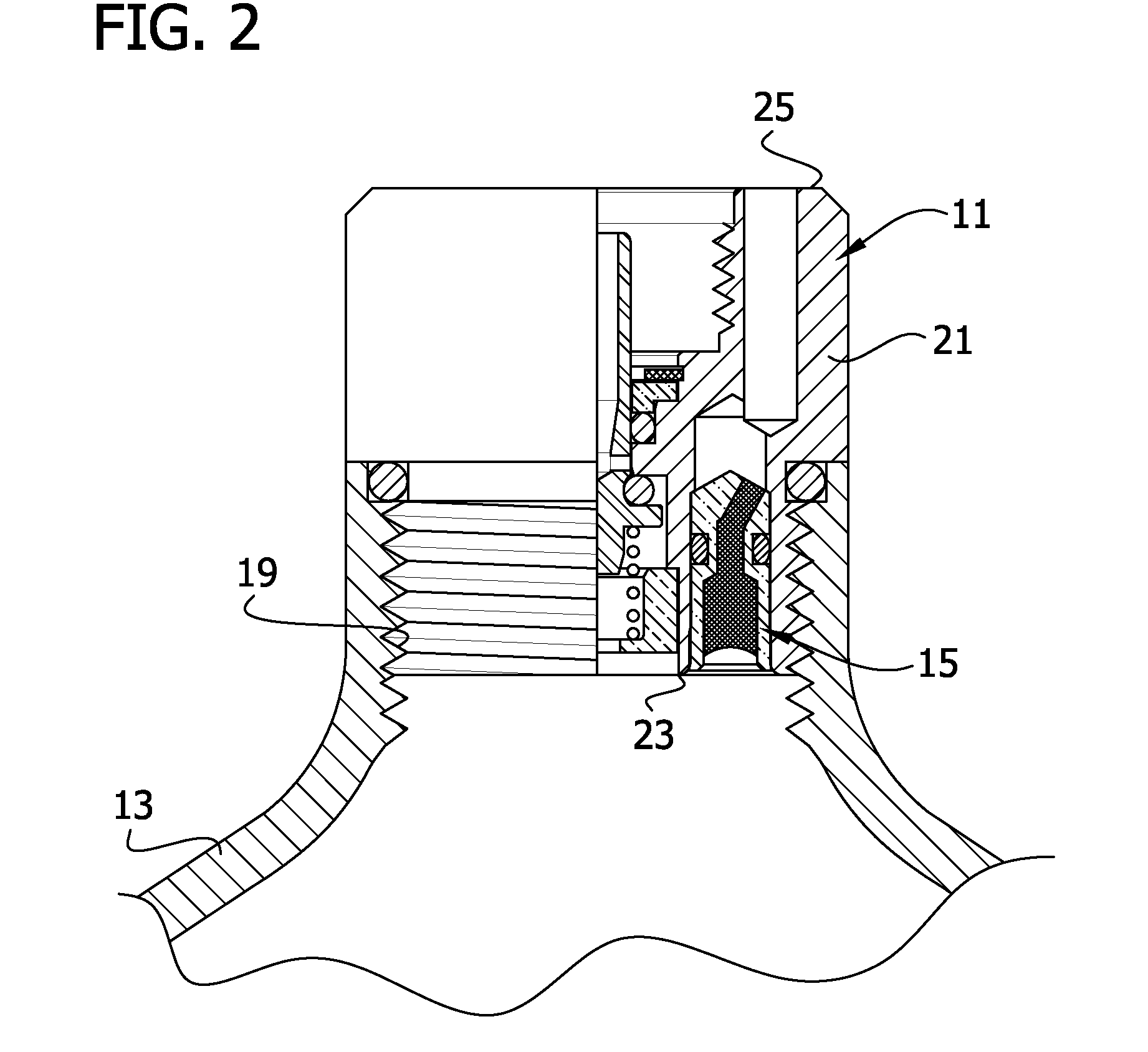
[0015]Referring now to the drawings, and in particular FIG. 2, a cylinder valve of the present invention is indicated in its entirety by the reference numeral 11. The valve is shown mounted on a cylinder 13 containing a mixture of gases under pressure, including a very low amount of a gas that is used for calibration, such as hydrogen sulfide (H2S). (This trace gas is hereinafter referred to as “calibration gas.”) The cylinder valve 11 has a thermal relief feature 15 for venting gas from the cylinder 13 in the event the temperature of the cylinder and / or gas inside the cylinder rises to a level above a predetermined temperature.

[0016]Referring to FIGS. 3 and 4, the cylinder valve 11 comprises a cylindrical valve body 21 having a front end 23, a back end 25, and a bore 27 defining a central flow passage 29 extending through the valve body from the front end to the back end for fluid communication with an interior of the cylinder 13 when the valve body is connected to the cylinder. Th...


PUM


Abstract

A cylinder valve for use with a cylinder containing fluid under pressure includes a valve body configured for releasable connection to the cylinder. The valve body has a flow passage extending through the valve body for fluid communication with an interior of the cylinder when the valve body is connected to the cylinder. A valve in the flow passage is movable between open and closed positions. A vent passage is in the valve body and is separate from the flow passage. A temperature relief insert is in the vent passage. The insert includes an insert body, a bore through the insert body, and a thermal relief material in the bore blocking flow through the bore until a predetermined venting temperature is reached. The valve body does not contain brass and the insert body is brass covered by a metal plating not containing brass.

Description

FIELD OF THE INVENTION[0001]The present invention generally relates to cylinder valves, and more particularly to a cylinder valve for use with cylinders containing a gas under pressure.BACKGROUND OF THE INVENTION[0002]Sensors are used to monitor the permissible levels of certain gases (e.g., hydrogen sulfide) in working environments. These sensors must be tested from time to time to make sure they are sufficiently sensitive to the presence of such gases. One test method involves the use of a cylinder containing a mix of gases including trace amounts of the gas or gases to be monitored. The gaseous mixture is released from the cylinder in the vicinity of the sensor to confirm that the sensor is working and that it is properly calibrated. To insure accurate test results, it is important that the mixture of gases in the cylinder remains stable over time.[0003]In conventional cylinder designs, a valve with a thermal relief feature is connected to the cylinder to vent the cylinder in the...

Claims


Application Information

Patent Timeline
Patent Type & Authority Applications(United States)
IPC IPC(8): F17C13/06F16K17/38
CPCF16K1/307F17C2260/05F17C13/04F17C2201/0104F17C2205/0317F17C2205/0323F17C2205/0332F17C2205/0335F17C2205/0338F17C2205/0385F17C2205/0394F17C2221/03F17C2221/037F17C2223/0123F17C2223/035F16K17/383Y10T137/1812
Inventor LAMMERS, DANIEL A.
Owner CONTROL DEVICES
Why Eureka
Try Eureka