Digital micromirror device module

a digital micromirror and module technology, applied in the field of digital micromirror device modules, can solve the problems of increasing costs of compression springs and multi-section screws, complex design of conventional dmd modules with many elements, and non-uniform thermal load distribution, etc., to achieve the effect of reducing costs and simplifying the structur

Inactive Publication Date: 2010-02-09
CORETRONIC
View PDF7 Cites 13 Cited by
  • Summary
  • Abstract
  • Description
  • Claims
  • Application Information

AI Technical Summary

Benefits of technology

[0007]The present invention relates to a DMD module with simplified structure and reduced costs.
[0012]In the embodiment of the invention, the distance between the heat sink and the circuit board and the distance between the heat sink and the DMD element are modified simultaneously by the fixers. Therefore, the electrical load is modified by modifying thickness and material of the soft elastic pad, and the thermal load is modified by modifying thickness and material of the heat dissipation pad. Compared to the conventional art utilizing shoulder screws and push nuts to control electrical load and thermal load, the DMD module of the embodiment of the invention has no shoulder screws, no compression springs telescoped on fixers, and no additional O-rings or E-rings. The DMD module of the embodiment of the invention is easier to assemble, with a simplified structure and reduced costs. Compression quantities of the soft elastic pad and the heat dissipation pad are uniform, and thermal load distribution and heat dissipation are thus improved. Additionally, the soft elastic pad of rubber, insulates the heat sink from the circuit board, and prevents the circuit board from being scratched.

Problems solved by technology

Conventional DMD modules are complicated designed with many elements, for example, compression springs are telescoped on the multi section screws.
The compression springs and multi section screws increase costs.
Furthermore, the compression quantity of each compression spring differs from one another, thus, thermal load distribution is non-uniform, and heat dissipation is un-uniform.
Additionally, for conventional DMD modules, O-rings or E-rings are required to be disposed between the heat sink and the flat spring, and further increase costs.
Meanwhile, the flat spring may conduct the heat sink and the circuit board, and scratch the circuit board.

Method used


Image

  • Digital micromirror device module
  • Digital micromirror device module
  • Digital micromirror device module

Examples


Embodiment Construction

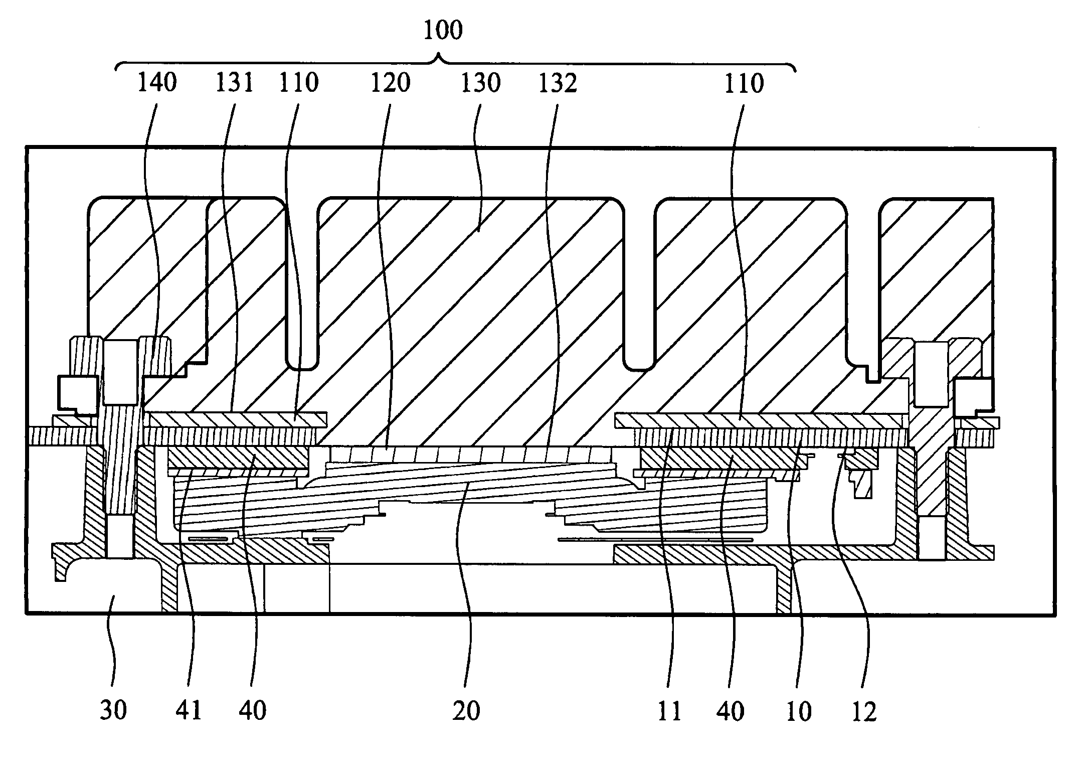
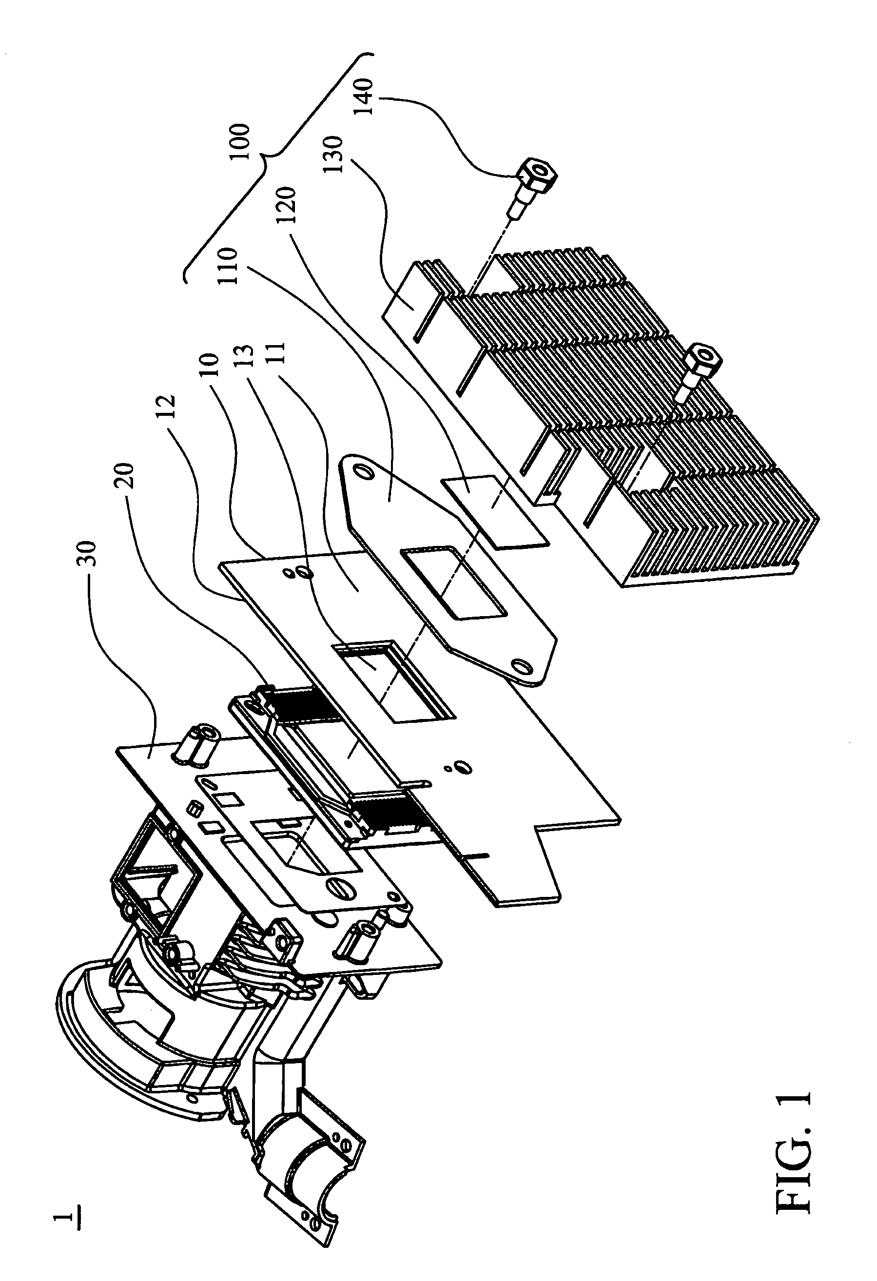
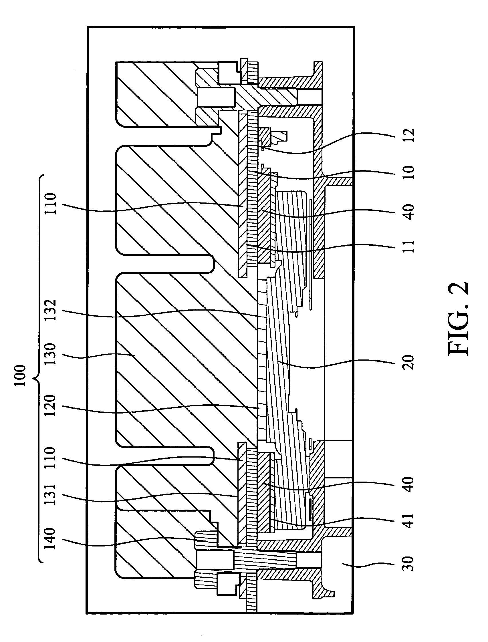
[0018]In the following detailed descriptions of the embodiments of the present invention, reference is made to the accompanying drawings which form a part hereof, and in which are shown by way of illustration the method in which the present invention may be practiced. In this regard, directional terminology, such as “top,”“bottom,”“front,”“back,” etc., is used with reference to the orientation of the Figure(s) being described. Meanwhile, the components of the present invention can be positioned in a number of different orientations. As such, the directional terminology is used for purposes of illustration and is by no means limiting. Additionally, the drawings are only schematic and the sizes of components may be exaggerated for clarity. It is also to be understood that other embodiments may be utilized and structural changes may be made without departing from the general scope of the present invention. Also, it is to be understood that the phraseology and terminology used herein is...


PUM


Abstract

A digital micromirror device (DMD) module includes a circuit board, a DMD element, a soft elastic pad, a heat dissipation pad and a heat sink. The circuit board includes a first surface, a second surface and a through hole, wherein the first surface is opposite to the second surface. The DMD element is electrically connected to the circuit board. The soft elastic pad is disposed on the first surface of the circuit board and surrounds the through hole. The heat dissipation pad passes through the through hole and contacts the DMD element. The soft elastic pad is sandwiched between the circuit board and the heat sink, the heat dissipation pad is sandwiched between the heat sink and the DMD element, and the heat sink contacts the soft elastic pad and the heat dissipation pad, so as to apply a force to the soft elastic pad and the heat dissipation pad.

Description

CROSS REFERENCE TO RELATED APPLICATIONS[0001]This application claims priority of Taiwan Patent Application No. 096144933, filed on Nov. 27, 2007, the entirety of which is incorporated by reference herein.BACKGROUND OF THE INVENTION[0002]1. Field of the Invention[0003]The present invention relates to a Digital Micromirror Device (DMD) module, and more particularly to a DMD module with a simplified structure.[0004]2. Description of the Related Art[0005]In a Digital Micromirror Device (DMD) module, an electrical load controlling the electrical connection states and a thermal load controlling the heat connection states are adjusted according to the designing style of the DMD element, so as to improve electrical conduction and heat dissipation effect. Conventional DMD modules, for example, a DMD module made by Texas Instruments, utilizes shoulder screws and push nuts to control electrical load and thermal load, separately. Additionally, compression springs and flat springs are utilized i...

Claims


Application Information

Patent Timeline
Patent Type & Authority Patents(United States)
IPC IPC(8): H05K7/20
CPCH05K7/20472G02B26/0833
Inventor CHEN, JUNG-CHICHEN, CHE-HSUEH
Owner CORETRONIC
Why Eureka
Try Eureka