Optical deflector, optical scanner, image forming apparatus, and image projector

Active Publication Date: 2010-12-09
RICOH KK
View PDF2 Cites 41 Cited by
  • Summary
  • Abstract
  • Description
  • Claims
  • Application Information

AI Technical Summary

Benefits of technology

[0013]Accordingly, an object of the present invention is to provide a compact o

Problems solved by technology

However, the optical deflector with a pectinate electrode cannot obtain a sufficient deflection angle of a light beam and has to make up for that with a large drive voltage.
However, the parts needed for such an electric source become large to enlarge the drive voltage, resulting in growth in size of the deflector and an increase in cost.
As for the optical deflector using an electromagnetic force, the magnetic force of a permanent magnet or a current of the coil needs increasing, resulting in growth in size of the deflector and an increase in electric power consumption.
A deflector using a magnetostrictive film is available to downsize the deflector, but has poor magnetic properties.
When current flows through the coil, extra heat is generated, resulting in an increase in electric power consumption as well.
Meanwhile, although the deflector using a piezoelectric force needs a comparatively large drive voltage, it can generate a large force with a small amount of electric power.
However, the conventional optical deflectors using a piezoelectric force still have various problems.
However, the bulk piezoelectric element app

Method used


Image

  • Optical deflector, optical scanner, image forming apparatus, and image projector
  • Optical deflector, optical scanner, image forming apparatus, and image projector
  • Optical deflector, optical scanner, image forming apparatus, and image projector

Examples


example 1

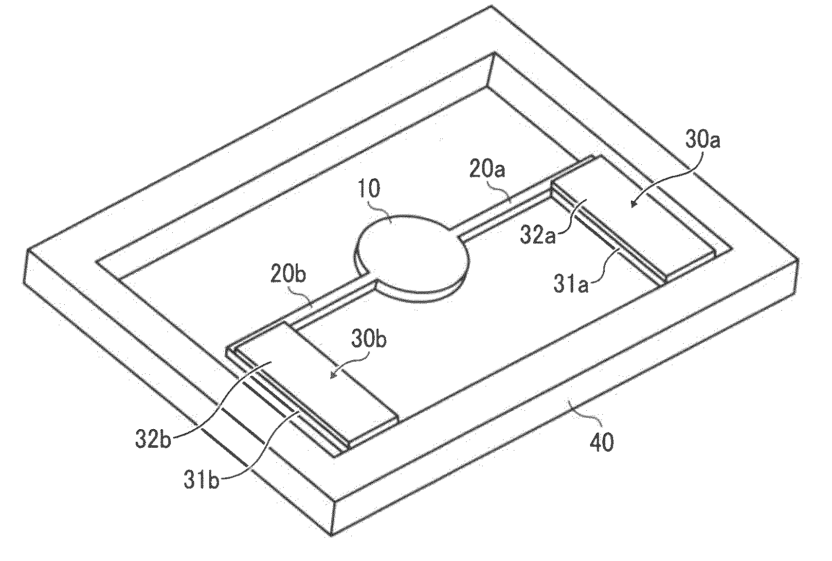
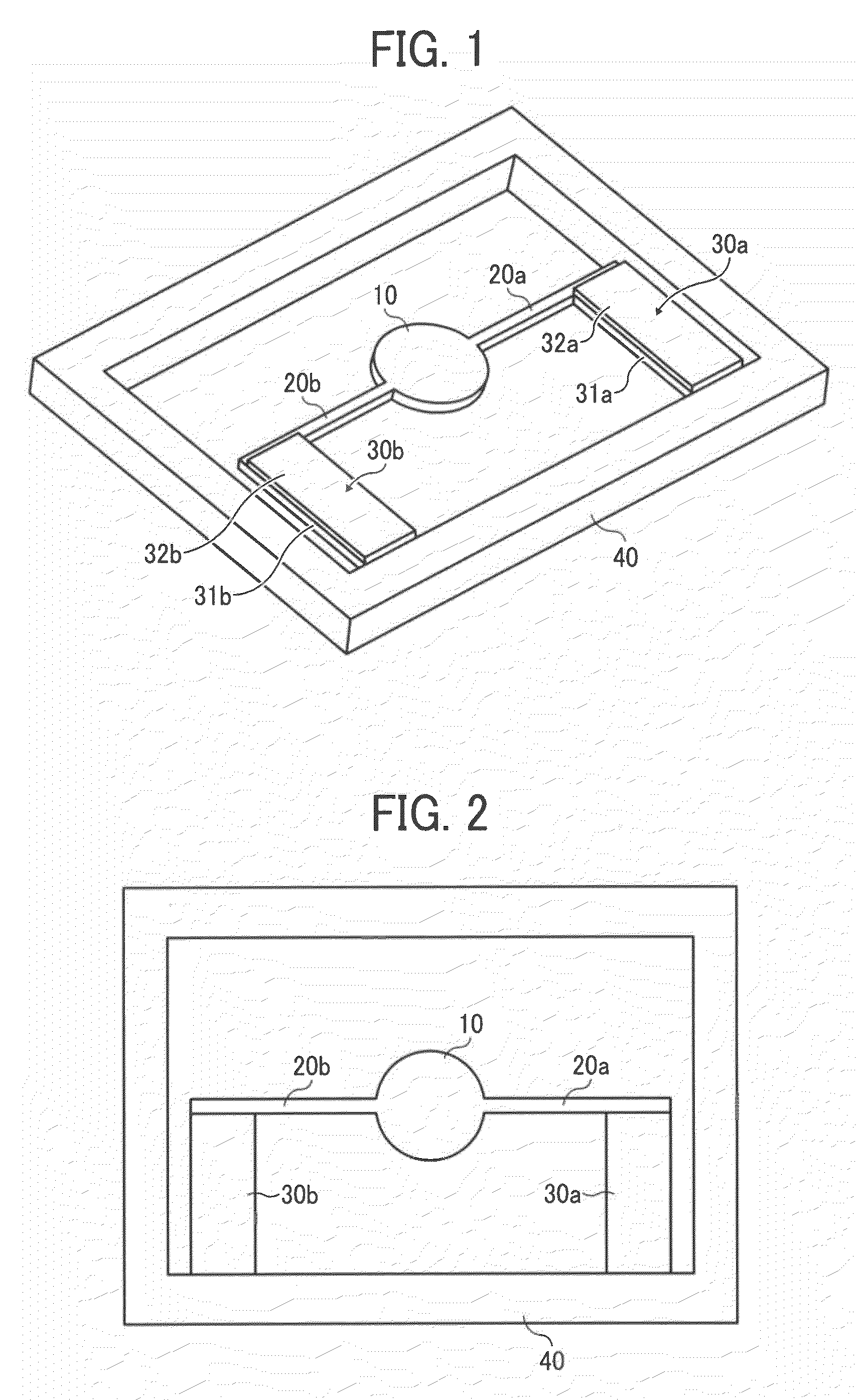
[0065]FIG. 1 is an overall perspective view of the optical deflector in Example 1 of the present invention, and FIG. 2 is a plain view thereof. In FIGS. 1 and 2, numeral 10 is a mirror having a reflection surface reflecting light, and torsion bar springs 20a and 20b as a pair of elastic support members oscillatably supporting the mirror 10 are connected with both ends of thereof. In Example 1, the (gravity) center of the mirror 10 conforms to the central axes of the torsion bar springs 20a and 20b. The other ends of the torsion bar springs 20a and 20b, which are opposite to the mirror, are connected with ends of a pair of beam-shaped members 31a and 31b in a direction almost orthogonal to a longitudinal direction of the torsion bar springs 20a and 20b as a longitudinal direction. The other ends of the beam-shaped members 31a and 31b are connected with a fixed base 40.

[0066]The beam-shaped members 31a and 31b are located only one side of the torsion bar springs 20a and 20b, respectiv...

example 2

[0078]FIG. 6 is a perspective view illustrating another embodiment of the optical deflector of the present invention in Example 2, and FIG. 7 is a plain view thereof. Parts in FIGS. 6 and 7 which are the same as those in FIGS. 1 and 2 have the same numbers therein.

[0079]As shown in FIG. 7, the (gravity) center O of the mirror 10 is offset for a distance ΔS in a direction close to connection points between each of the torsion bar springs 20a and 20b and the fixed base 40. Thus, flexural deformations of the drive beams 30a and 30b can rotationally oscillate the mirror 10 more largely than Example 1. The driving method is the same as that of Example 1.

[0080]FIG. 8 is a diagram showing a frequency response characteristic of an amplitude of a rotational angle of the mirror 10 to a voltage applied to the piezoelectric materials 32a and 32b of the drive beams 30a and 30b when the center of gravity of the mirror 10 is offset. FIGS. 9A and 9B are schematic views illustrating characteristic o...

example 3

[0083]FIG. 11 is a perspective view illustrating a further embodiment of the optical deflector of the present invention in Example 3. Parts in FIG. 11 which are the same as those in FIG. 1 have the same numbers therein. The total configuration is the same as that in Example 1. Dents 50a and 50b are formed on a connection point between each of the drive beams 30a and 30b and the torsion bar springs 20a and 20b so that the thickness in a direction (Z direction) perpendicular to the mirror surface of the mirror 10 may be partially small. Thus, the flexural deformation of the drive beams 30a and 30b basally rotates the torsion bar springs 20a and 20b, and the rotation amplitude of the mirror 10 can further be increased.

[0084]FIG. 12 a partially-amplified perspective view illustrating a connection between the drive beam 30b and the torsion bar spring 20b. As FIG. 12 shows, a bump on a connection point between the beam-shaped member 31b and the torsion bar spring 20b can easily form the d...


PUM


Abstract

An optical deflector, including a fixed base; a mirror having a light reflection surface; a pair of elastic support members oscillatably supporting the mirror; and a pair of drive beams formed of a beam-shaped member on which a piezoelectric is fixed, wherein the elastic support members and the drive beams in longitudinal directions are almost orthogonally located and connected with each other, other ends of the drive beams are fixed on the fixed base, the mirror and the pair of elastic support members are cantilevered by the pair of drive beams relative to the fixed base, and bending oscillation of the drive beams causes torsional deformation of the elastic members to rotationally oscillate the mirror.

Description

BACKGROUND OF THE INVENTION[0001]1. Field of the Invention[0002]The present invention relates to an optical deflector deflecting and scanning light beams such as laser beams, and more particularly to an optical deflector using piezoelectric force. Further, the present invention relates to an optical scanner using the optical deflector, an image forming apparatus using the optical scanner as an optical writing unit, and an image projector using the optical deflector as a scanning unit.[0003]2. Discussion of the Background[0004]Optical deflectors deflecting and scanning light beams such as laser beams are widely used in image forming apparatuses such as copiers, image projectors, laser beam printers, and barcode scanners. As such optical deflectors, optical deflectors using an electrostatic force, an electromagnetic force, and a piezoelectric force are conventionally known.[0005]The optical deflectors using an electrostatic force include those with an electrode having the shape of a p...

Claims


Application Information

Patent Timeline
IPC IPC(8): G02B26/10
CPCG02B26/0858
Inventor AKANUMA, GOICHIKITAZAWA, TOMOFUMISAKOH, FUMIKOFUJII, MITSUMI
Owner RICOH KK
Why Eureka
Try Eureka