Display wall mount with elastomeric spring latch and post-installation height adjustment and leveling feature

a technology of elastomeric spring latches and display wall mounts, which is applied in the direction of television systems, electrical apparatus casings/cabinets/drawers, instruments, etc., can solve the problems of difficult mounting modifications during installation, difficult to completely remove the display from the wall, and many prior mounts that have been somewhat difficult to install and adjust, etc., to achieve the effect of improving the versatility of movement, maintenance and manipulation

Active Publication Date: 2010-12-09
LEGRAND AV INC
View PDF28 Cites 49 Cited by
  • Summary
  • Abstract
  • Description
  • Claims
  • Application Information

AI Technical Summary

Benefits of technology

[0007]The present invention addresses the need of the industry for a flat panel display mount that provides enhanced versatility of movement and ease of installation, maintenance, and manipulation. According to embodiments of the invention, a mount for attaching an electronic display to a wall includes a support structure adapted to attach to the wall and presenting a pair of vertically spaced-apart generally horizontally oriented flanges. The mount further includes a pair of display interface brackets, each of the display interface brackets including a display interface portion adapted to attach to the electronic display, and a hook bracket assembly operably coupled to the display interface bracket. The hook bracket assembly presents a hook selectively engagable over an upper one of the flanges of the support structure to hang the display interface brackets and the display from the support structure and further includes a vertical position adjustment assembly operably coupled to the display interface bracket. The vertical position adjustment assembly enables selective vertical positioning of the display interface portion and the display relative to the support structure.

Problems solved by technology

Many prior mounts have been somewhat difficult to install and adjust as access to the area behind a flat panel display is often very limited during and after the installation process.
Moreover, because many larger displays are heavy and hard to lift and position, it is very difficult to make mounting modifications during installation without completely removing the display from the wall.

Method used


Image

  • Display wall mount with elastomeric spring latch and post-installation height adjustment and leveling feature
  • Display wall mount with elastomeric spring latch and post-installation height adjustment and leveling feature
  • Display wall mount with elastomeric spring latch and post-installation height adjustment and leveling feature

Examples


Embodiment Construction

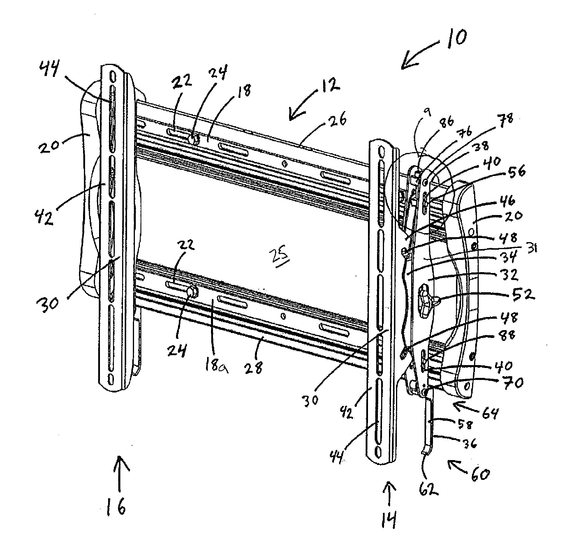
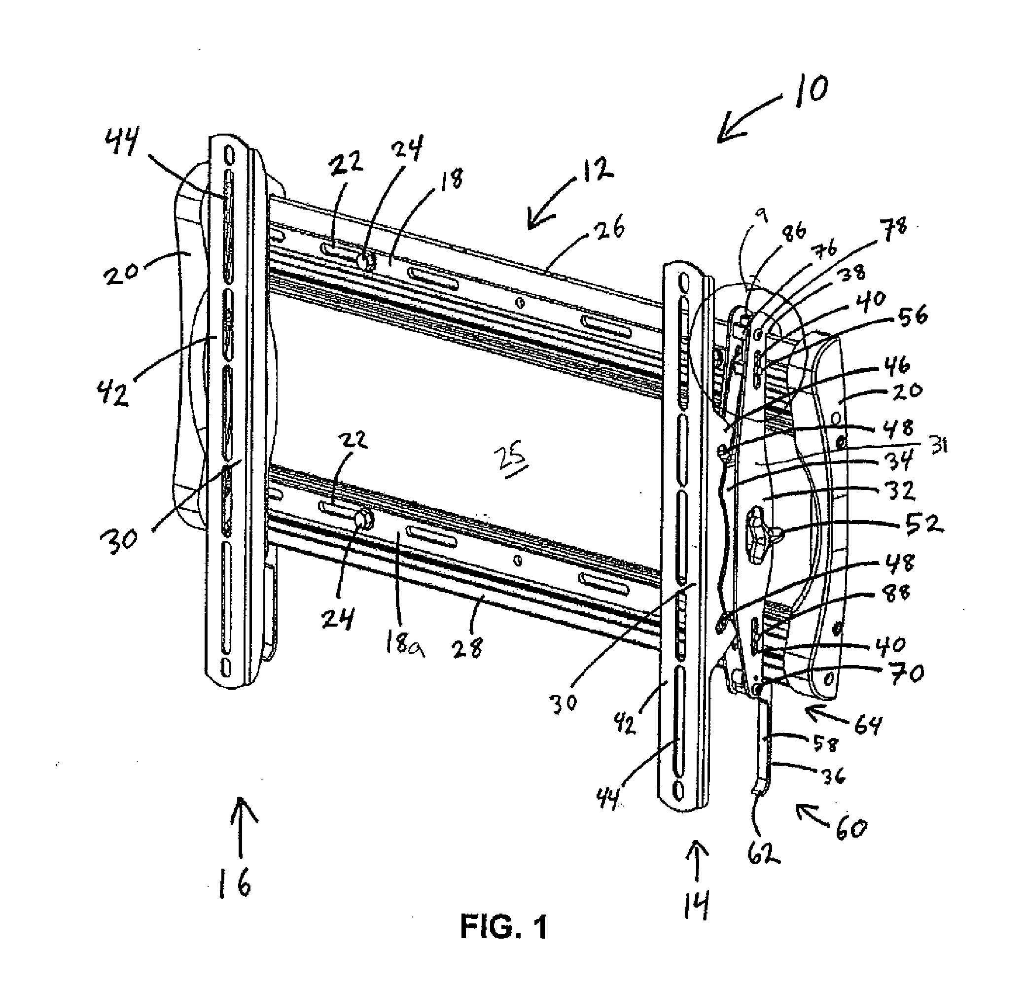
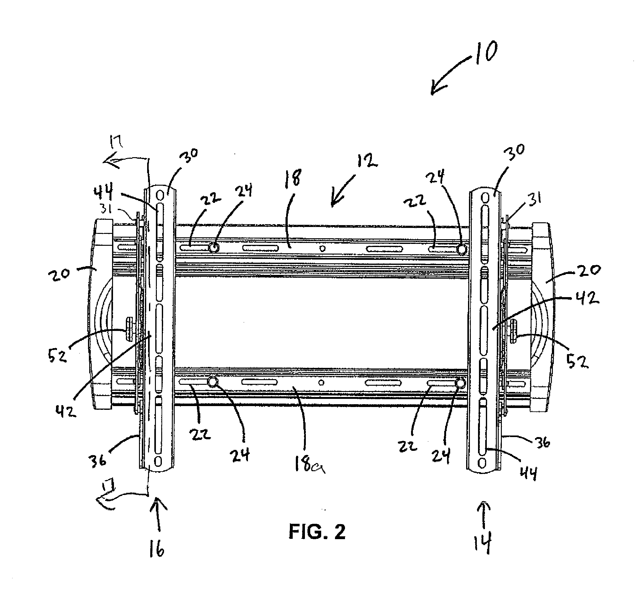
[0051]Embodiments of the present invention relate to display mount systems for attaching a flat panel electronic display to a fixed structure. Such flat panel displays include plasma displays, liquid crystal displays (LCDs), or any other kind of electronic display that is of similar dimensions or characteristics. Fixed structures generally refer to walls, but also may include ceilings, beams, columns, pieces of furniture, booths, or any other fixed or permanent structure to which a display mount might be attached.

[0052]An embodiment of a display wall mount 10 is depicted in FIGS. 1 through 14a. Display wall mount 10 generally includes support assembly 12 and first and second display interface bracket assemblies 14, 16. Support assembly 12 generally includes two parallel, transversely disposed, spaced-apart supports 18, 18a, that are fixed together at their ends by vertical support members 20. Supports 18, 18a, define a series of openings 22 that receive fasteners 24 to mount support...


PUM

PropertyMeasurementUnit
elastomericaaaaaaaaaa
weightaaaaaaaaaa
sizeaaaaaaaaaa

Abstract

A mounting system for an electronic display providing enhanced versatility of movement and ease of installation. The mounting system includes a latch and kickstand assembly for latching the display to a support structure mountable to a wall and propping the bottom edge of the display away from the wall to enable connection of wires to the back of the display while the display is mounted on the wall. The mount further includes a vertical position adjustment assembly to enable vertical positioning and leveling of the display after the display is mounted.

Description

RELATED APPLICATIONS[0001]This application claims the benefit of U.S. Provisional Patent Application No. 60 / 970,429, filed Sep. 6, 2007, hereby fully incorporated herein by reference.FIELD OF THE INVENTION[0002]The present invention relates generally to mounts for video display devices, and more particularly to mounts for flat panel displays.BACKGROUND OF THE INVENTION[0003]Flat panel monitors and televisions have become highly popular and widely used throughout commercial, business, and residential environments. These flat panel displays enable an enhanced viewing experience with layout versatility, space savings, and the ability to replace bulky computer monitors and televisions with displays that are merely a fraction of the depth and weight of similar prior displays of identical screen size.[0004]The dimensional characteristics of the displays allow them to be conveniently hung on a wall or connected to a mounting surface such as a column, post, or flat surface of a piece of fur...

Claims


Application Information

Patent Timeline
Patent Type & Authority Applications(United States)
IPC IPC(8): H05K7/00F16M13/02
CPCF16M11/10F16M11/24F16M13/02Y10T29/49826F16M2200/041H04N5/64H05K7/14F16M2200/022
Inventor GREY, DOMINICPFISTER, JOELTRIBUNO, PETER
Owner LEGRAND AV INC
Why Eureka
Try Eureka