LED light bar with a replaceable power source

a technology of power source and led light bar, which is applied in the field of led light bar with a replaceable power source structure, can solve the problems of difficult estimation of the failure risk of electronic elements in the power supply b>94/b>, unstable waveform, and inability to light up new ones

Inactive Publication Date: 2010-12-09
IOVISION PHOTOELECTRIC +1
View PDF9 Cites 48 Cited by
  • Summary
  • Abstract
  • Description
  • Claims
  • Application Information

AI Technical Summary

Benefits of technology

[0013]The invention is further characterized in that the connector on one end of the base is provided with a power supply. The base has connector base for the power supply on that end. The power supply and the connector base can be fixed units that can be separated and assembled. They have quick-connect terminals for the power supply to electrically connect to the lamp. The connectors on both ends of the base have a first terminal and a second terminal, respectively. The first terminal of each of the connectors electrically connects to the corresponding electrode on the power supply. The two second terminals are connected in series with a capacitor for stabilizing the voltage.

Problems solved by technology

Although the LED has the features of power-saving and long lifetime, the risk for the electronic elements in the power supply 94 to fail is difficult to estimate.
However, when the two fluorescent lamps are replaced by lamps of other specifications, the new ones cannot be lit up.
One is higher than the other, rendering an unstable waveform.
This low compatibility is one of the problems in the prior art.

Method used


Image

  • LED light bar with a replaceable power source
  • LED light bar with a replaceable power source
  • LED light bar with a replaceable power source

Examples


Embodiment Construction

[0026]The present invention will be apparent from the following detailed description, which proceeds with reference to the accompanying drawings, wherein the same references relate to the same elements.

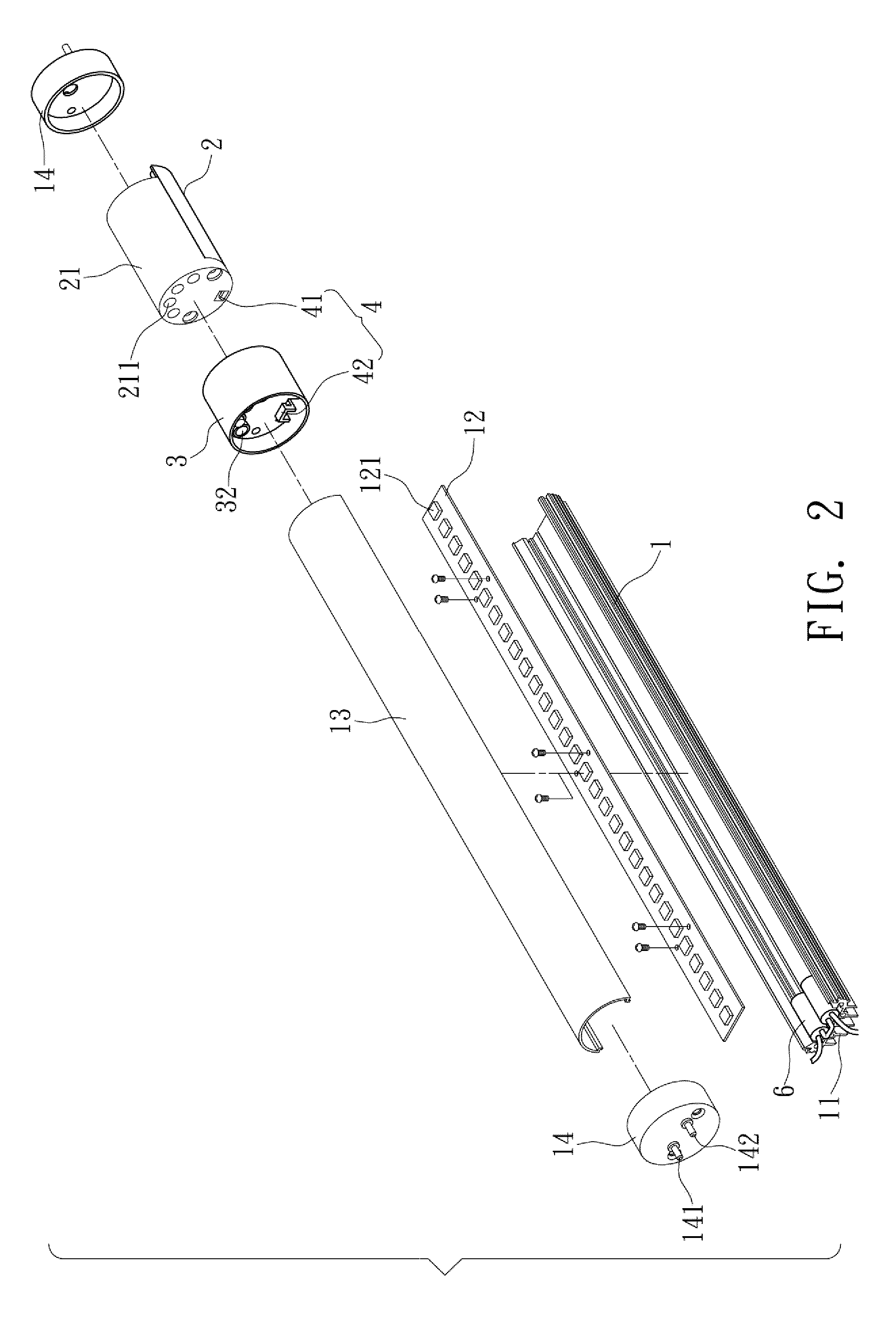
[0027]Please refer to FIGS. 1 and 2, which show an embodiment structure of the invention. It is only for the purpose of illustration. The invention is not limited to this particular structure.

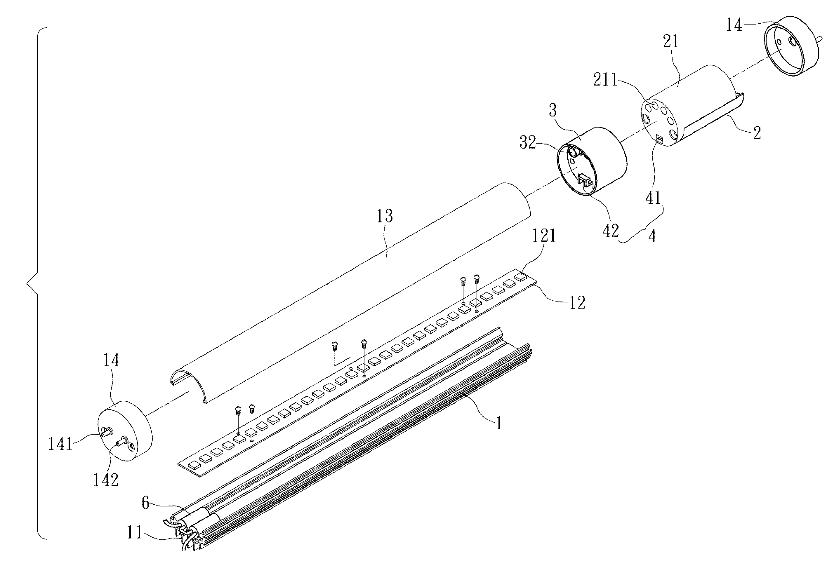
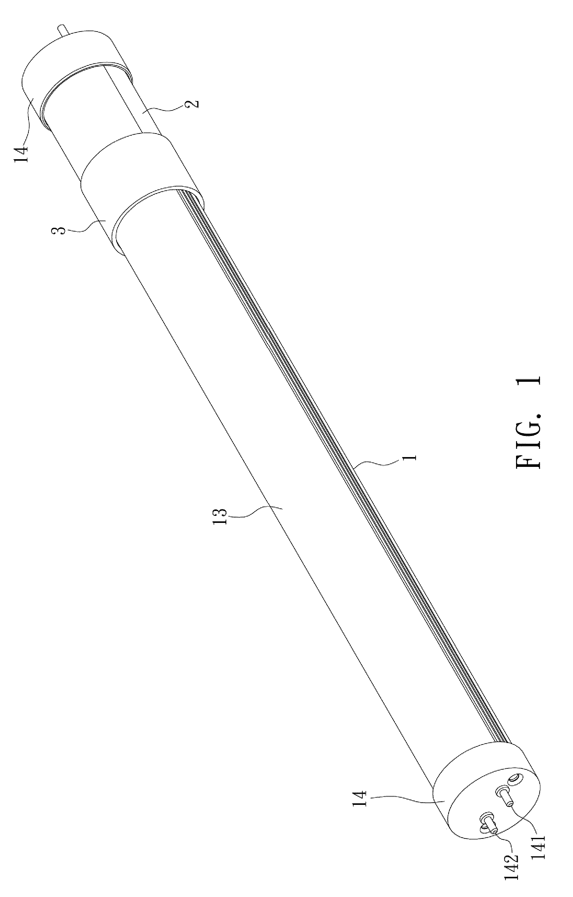
[0028]This embodiment provides an LED light bar with a replaceable power source. It includes a base 1 and a power supply.

[0029]The base 1 has a heat-dissipating structure 11 and is disposed with a lamp 12. The lamp 12 uses an LED 121 as its light-emitting element. A lampshade 13 covers the lamp 12 from the base 1. Each of the two ends of the base 1 has a connector 14 electrically connected to the lamp base.

[0030]The power supply 2 is disposed at the connector 14 on one end of the base 1. The base 1 also has a connector base 3 on that end for the power supply 2 to mount and connect. Moreover, a fi...


PUM


Abstract

An LED light bar with a replaceable power source. A base is inserted with an LED lamp. A lampshade covers the lamp. Both ends of the base have a connector. One connector is connected with a power supply. A connecting base is provided between the power supply and the end portion of the base. This forms the disclosed LED light bar with a replaceable power supply.

Description

BACKGROUND OF THE INVENTION[0001]1. Field of Invention[0002]The invention relates to a light bar and, in particular, to an LED light bar with a replaceable power source structure.[0003]2. Related Art[0004]FIG. 7 shows a conventional light-emitting diode (LED) light bar. An LED lamp 91 is inserted on a base 90. A lampshade 92 covers the lamp 91. Both ends of the base 90 have connector 93, respectively, for electrically connecting with the base 90. The end portion of the lamp 91 is disposed with a power supply 94.[0005]When the above-mentioned conventional light bar starts, the power supply 94 at the end portion of the lamp 91 supplies the electrical power. Although the LED has the features of power-saving and long lifetime, the risk for the electronic elements in the power supply 94 to fail is difficult to estimate. Its lifetime cannot match with that of the lamp 91. Therefore, when the power supply 94 fails, one has to replace the entire set of light bar. This is a waste.[0006]As sh...

Claims


Application Information

Patent Timeline
Patent Type & Authority Applications(United States)
IPC IPC(8): F21L4/00
CPCF21K9/17F21K9/175F21S4/008F21V29/004F21Y2101/02F21Y2103/003F21V29/77H05B33/0809F21V23/023F21V29/507F21V29/75F21V29/763H05B33/0803F21S4/28F21Y2103/10F21Y2115/10F21K9/272F21K9/278H05B45/00
Inventor SHEN, FENG-JUIWANG, CHIEN-CHINYANG, SHIH-HSU
Owner IOVISION PHOTOELECTRIC
Why Eureka
Try Eureka