Integrated circuit system with dynamic decoupling and method of manufacture thereof

Active Publication Date: 2015-10-06
ALTERA CORP
View PDF10 Cites 0 Cited by
  • Summary
  • Abstract
  • Description
  • Claims
  • Application Information

AI Technical Summary

Benefits of technology

[0007]Embodiments of the present invention provide a method of manufacture of an integrated circuit system including: providing a supply grid connected to an active component of an integrated circuit die; connecting a high voltage capacitor to the supply grid; connecting a low voltage decoupling capacitor

Problems solved by technology

Excessive voltage swings by the integrated circuit system can lead to faulty operation thereof.
Solutions to these problems have been long sought b

Method used


Image

  • Integrated circuit system with dynamic decoupling and method of manufacture thereof
  • Integrated circuit system with dynamic decoupling and method of manufacture thereof
  • Integrated circuit system with dynamic decoupling and method of manufacture thereof

Examples


second embodiment

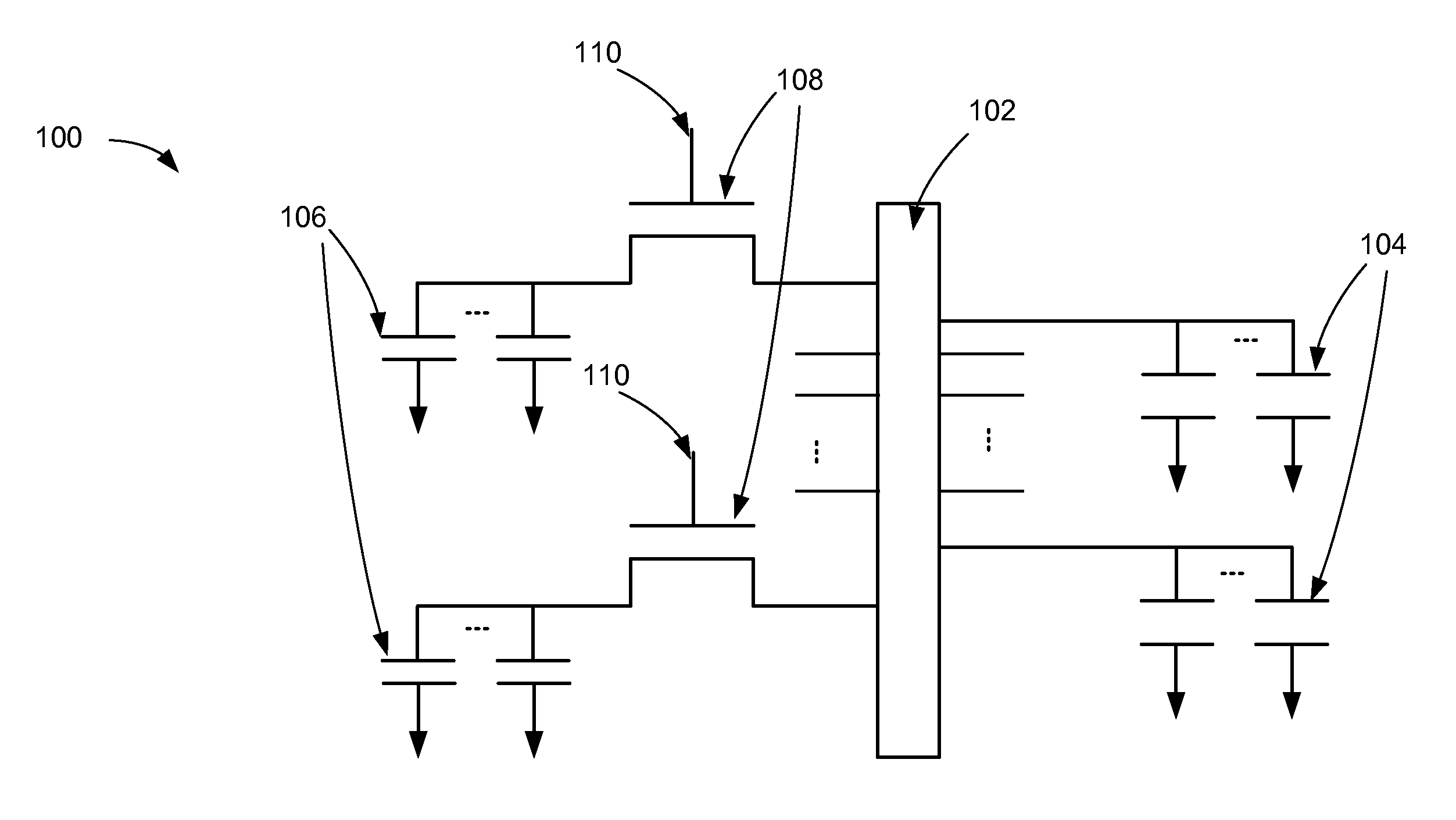
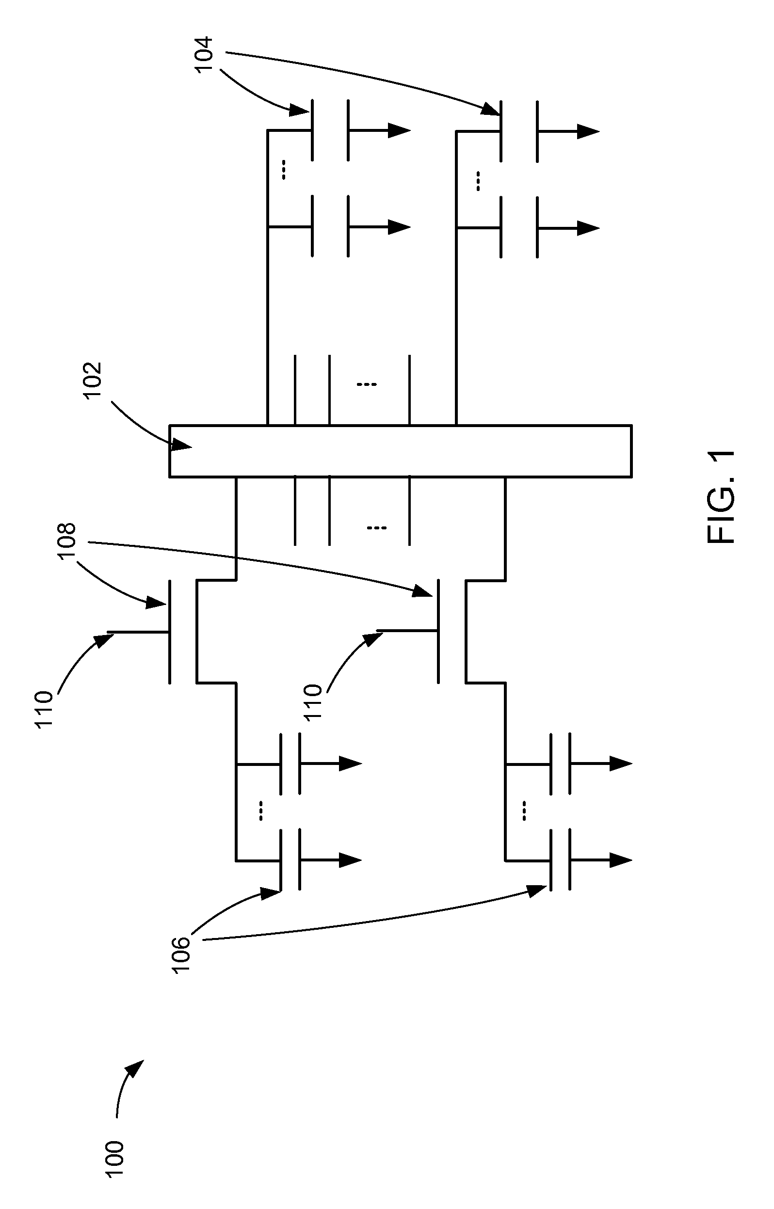
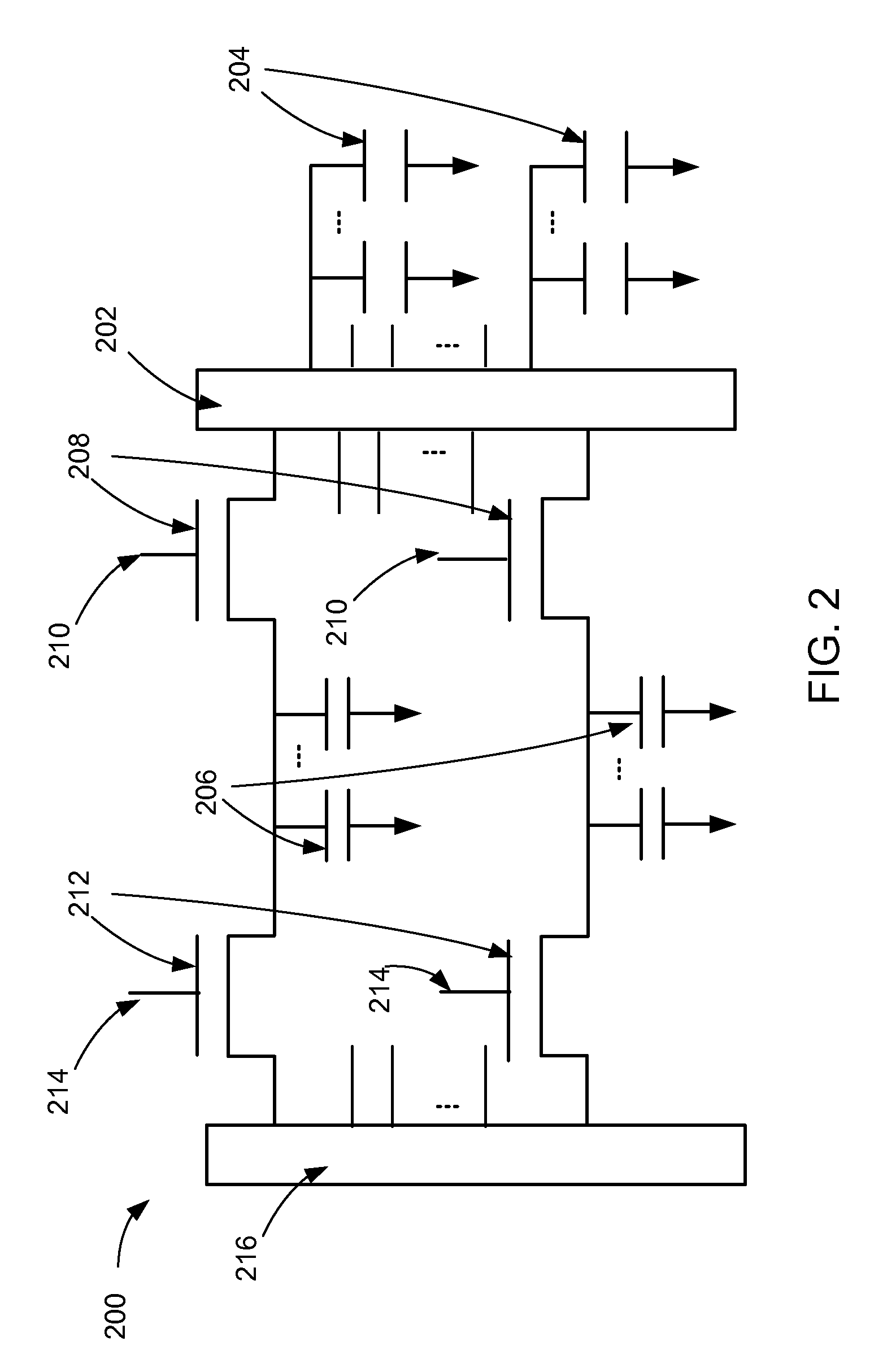
[0050]Referring now to FIG. 2, therein is shown a schematic of low voltage decoupling capacitors of an integrated circuit system 200 in the present invention. The integrated circuit system 200 can include an input / output (I / O) supply grid, such as power grid 202, high voltage capacitors 204, low voltage decoupling capacitors 206 which are mounted on a die of the integrated circuit system 200, input / output (I / O) pass gates 208, input / output (I / O) control 210, logic pass gates 212, a logic control 214, and a logic power grid 216.

[0051]A plurality of the high voltage capacitors 204 are shunted and connected to the power grid 202. The gates of the I / O pass gates 208 are connected together to the I / O control 210. The sources of the I / O pass gates 208 are connected to the power grid 202. A plurality of the low voltage decoupling capacitors 206 are shunted and connected to the drains of the I / O pass gates 208 and the drains of the logic pass gates 212. The gates of the logic pass gates 212...

third embodiment

[0058]Referring now to FIG. 3, therein is shown a schematic of low voltages decoupling capacitors of an integrated circuit system 300 in the present invention. The integrated circuit system 300 can include a power grid 302, high voltage capacitors 304, first low voltage decoupling capacitors 306 which is mounted on a die of the integrated circuit system 300, first pass gates 308, first low voltage control 310, second low voltage decoupling capacitors 312 which is mounted on a die of the integrated circuit system 300, second pass gates 314, and a second low voltage control 316.

[0059]A plurality of the high voltage capacitors 304 are shunted and connected to the power grid 302. The gates of the first pass gates 308 are connected together to the first low voltage control 310. The sources of the first pass gates 308 are connected to the power grids 302. A plurality of the first low voltage decoupling capacitors 306 are shunted and connected between the drains of the first pass gates 308...

fourth embodiment

[0072]Referring now to FIG. 4, therein is shown a schematic of low voltage decoupling capacitors of an integrated circuit system 400 in the present invention. The integrated circuit system 400 can include a power grid 402, high voltage capacitors 404, low voltage decoupling capacitors 406 which is mounted on a die of the integrated circuit system 400, pass gates 408, and a low voltage control 410.

[0073]A plurality of the high voltage capacitors 404 are shunted and connected to the power grid 402. The gates of the pass gates 408 are connected together to the low voltage control 410. The sources of the pass gates 408 are connected to grounds. A plurality of the low voltage decoupling capacitors 406 are shunted and connected between the drains of the pass gates 408 and the power grid 402.

[0074]The power grid 402 can support multiple voltages in a power distribution network of the integrated circuit system 400. The high voltage capacitors 404 are designed to meet the highest voltage req...


PUM


Abstract

A system and a method of manufacture of an integrated circuit system includes: a supply grid connected to an active component of an integrated circuit die; a high voltage capacitor connected to the supply grid; a low voltage decoupling capacitor connected to the supply grid; a pass gate gating the low voltage decoupling capacitor; and a pass gate control for controlling the pass gate to cause the high voltage capacitor and the low voltage decoupling capacitor to stabilize voltage of the supply grid during activity of the active component.

Description

TECHNICAL FIELD[0001]The present invention relates generally to an integrated circuits system, and more particularly to an integrated circuit system with dynamic decoupling.BACKGROUND ART[0002]An integrated circuit (IC) system, which includes structured application specific integrated circuits (ASICs) and field programmable gate arrays (FPGAs), are used to implement large systems that may include millions of gates and megabits of embedded memory. Switching activities of components in the integrated circuit system put stress on power distribution networks (PDNs) supporting it. The changing states of logic and memory elements require the integrated circuit power distribution networks to supply more power than if the logic and memory elements were operating in a constant state. When a large number of logic and memory elements change states simultaneously, a large demand is placed on the power distribution networks (PDNs). Excessive voltage swings by the integrated circuit system can le...

Claims


Application Information

Patent Timeline
IPC IPC(8): H03K17/16H03K19/003H03K19/00H01L27/02H03K17/081
CPCH01L27/0288H03K19/0013H03K19/00384H03K17/08104H03K19/00361
Inventor OH, KYUNG SUKSHUMARAYEV, SERGEY YURYEVICHLEE, HAE-CHANGANG, BOON JINCHEN, GUANG
Owner ALTERA CORP
Why Eureka
Try Eureka