Ignition enhancer for a vehicle engine
- Summary
- Abstract
- Description
- Claims
- Application Information
AI Technical Summary
Benefits of technology
Problems solved by technology
Method used
Image
Examples
Embodiment Construction
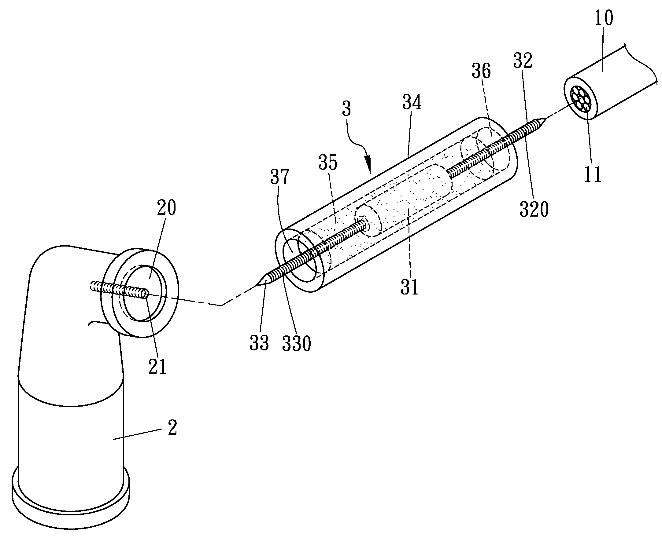
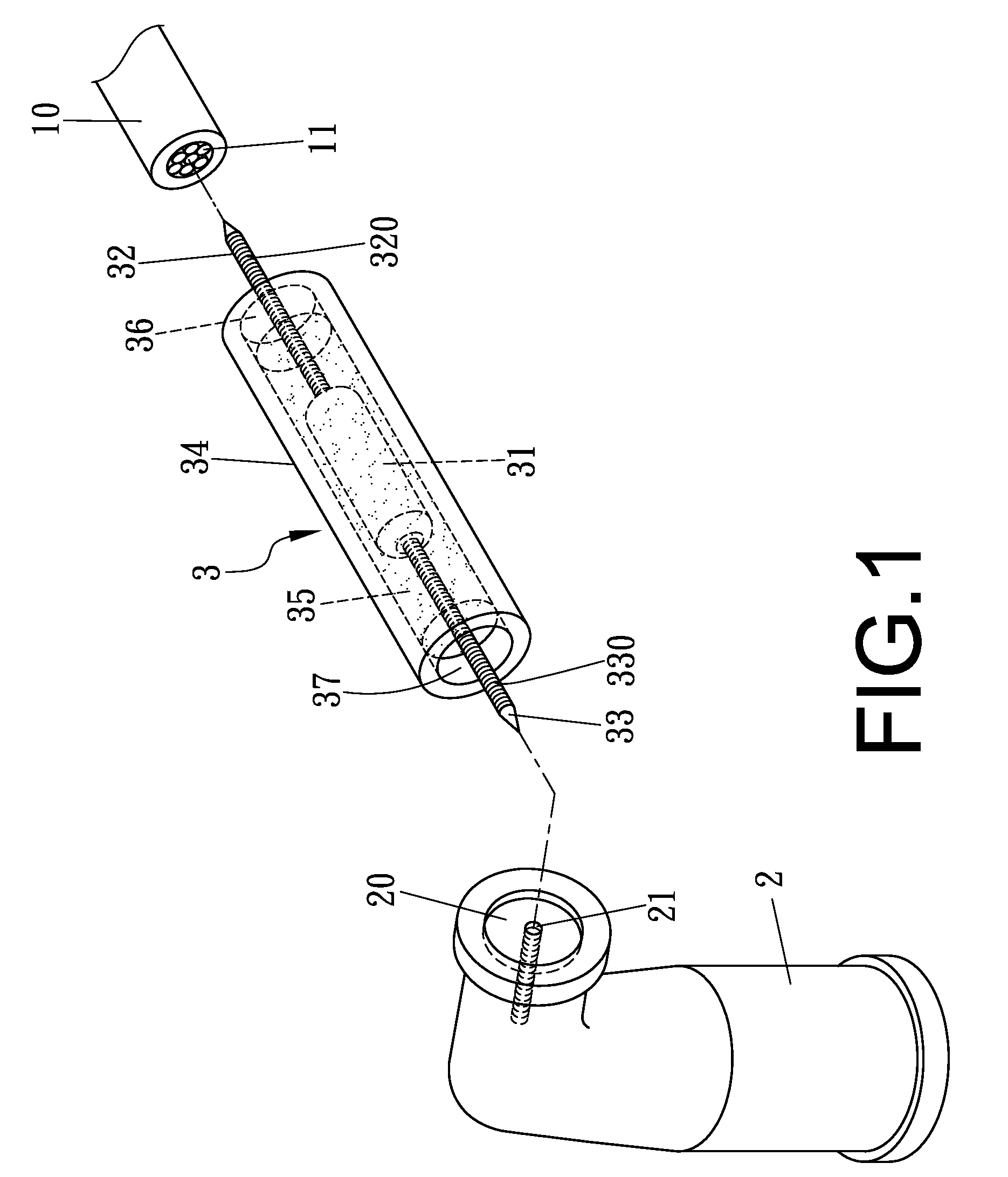
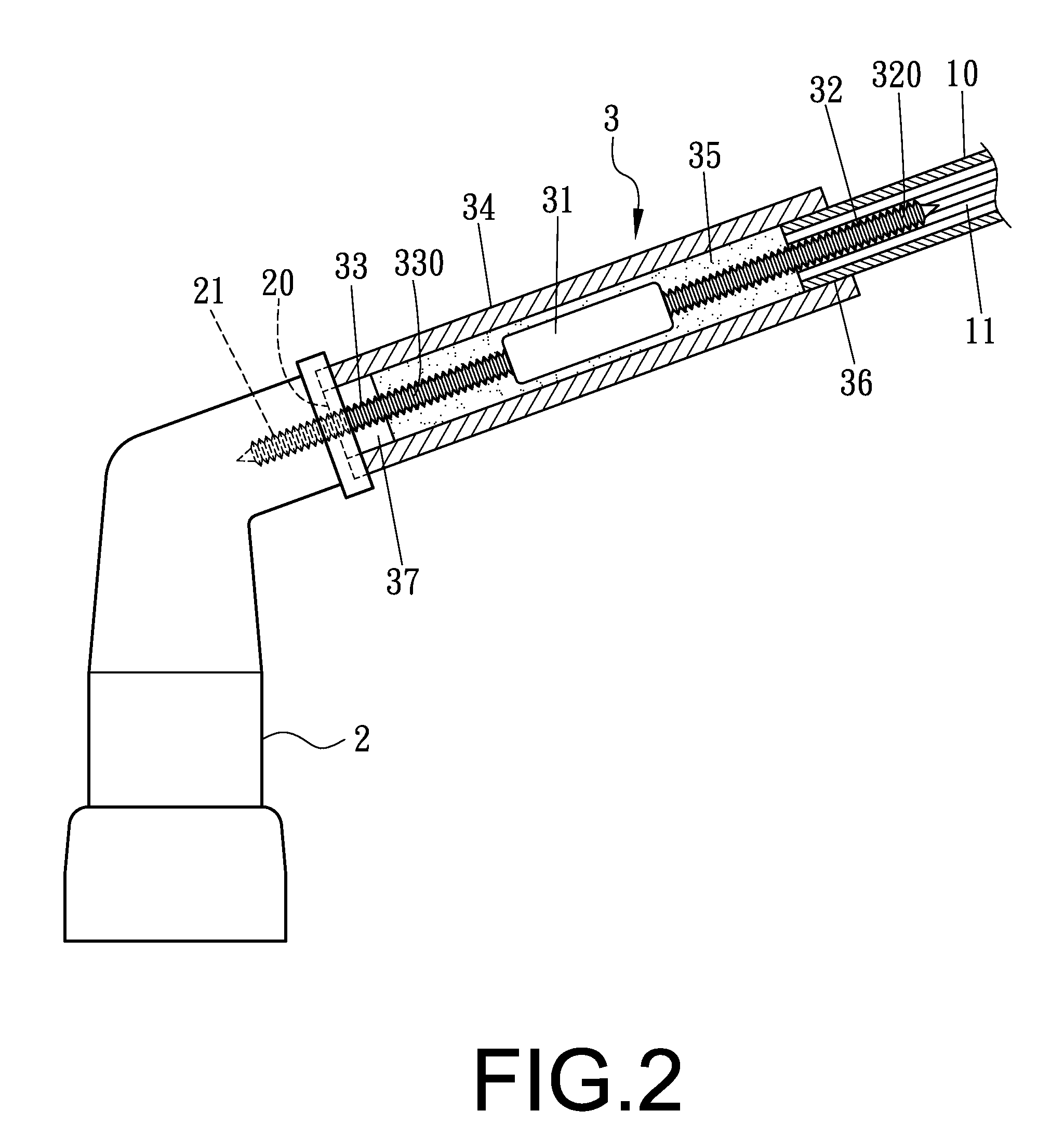
[0013]FIGS. 1 and 2 show a first preferred embodiment of an ignition enhancer 3 for a vehicle engine in the present invention. The ignition enhancer 3 is installed between a conducting wire 10 of a high voltage coil and a plug connector 2 provided with a groove 20 formed in one end and a female-threaded hole 21 bored inside the groove 20. The ignition enhancer 3 is provided with a capacitor 31, two conducting rods 32 and 33 respectively extended outward from two ends of the capacitor 31, an insulation sleeve 34 wrapping around the capacitor 31 and filled with waterproof resin 35 (Epoxy resin) to fully surround the capacitor 31, and two engaging grooves 36 and 37 respectively formed in two ends of the insulation sleeve 34. Each of the conducting rods 32 and 33 has male threads 320 and 330 formed around the surface respectively.
[0014]In assembling, an end of the conducting wire 10 of the high voltage coil is first plugged in the engaging groove 36 of the ignition enhancer 3, with the ...
PUM
 Abstract
Description
Claims
Application Information
 - R&D
- Intellectual Property
- Life Sciences
- Materials
- Tech Scout
- Unparalleled Data Quality
- Higher Quality Content
- 60% Fewer Hallucinations
Browse by: Latest US Patents, China's latest patents, Technical Efficacy Thesaurus, Application Domain, Technology Topic, Popular Technical Reports.
© 2025 PatSnap. All rights reserved.Legal|Privacy policy|Modern Slavery Act Transparency Statement|Sitemap|About US| Contact US: help@patsnap.com


