Velocity detecting device and multi-color image forming apparatus

a detection device and detection device technology, applied in the field of multi-color image forming apparatus, can solve the problems of color misregistration, large cost increase, low productivity,

Active Publication Date: 2010-12-09
RICOH KK
View PDF38 Cites 49 Cited by
  • Summary
  • Abstract
  • Description
  • Claims
  • Application Information

AI Technical Summary

Benefits of technology

[0014]It is an object of the present invention to at least partially solve the problems in the conventional technology.

Problems solved by technology

If the conveyor belt for feeding the recording medium such as a paper in the direct transfer system and the intermediate transfer belt in the intermediate transfer belt system are not driven with high accuracy, color misregistration will occur.
However, in the conventional technology described in the Japanese Patent Application Laid-open No. 2008-65743, because the direct formation of the mark on the intermediate transfer belt requires a quite lot of time and efforts, productivity is low, and this causes a large cost increase.
However, the conventional technology described in the Japanese Patent Application Laid-open No, 2003-266828 does not describe an optical system and does not also describe a method of correcting a detection error.
However, the conventional technology described in the Japanese Patent Application Laid-open No. 2007-283721 does not describe a detailed optical system and does not also describe a method of correcting a detection error.
Further, the detection is limited to the detection of the photosensitive drum because of the image forming apparatus.
However, the conventional technology described in the Japanese Patent Kohyo Publication No. 2007-519944 provides a detection condition optimized for generating a cipher signal by a speckle pattern, which is different in the purpose from an optimal detection condition for detecting a velocity of a moving object by the speckle pattern described in the present application, and the detection condition cannot easily be analogized.

Method used


Image

  • Velocity detecting device and multi-color image forming apparatus
  • Velocity detecting device and multi-color image forming apparatus
  • Velocity detecting device and multi-color image forming apparatus

Examples


implementation examples

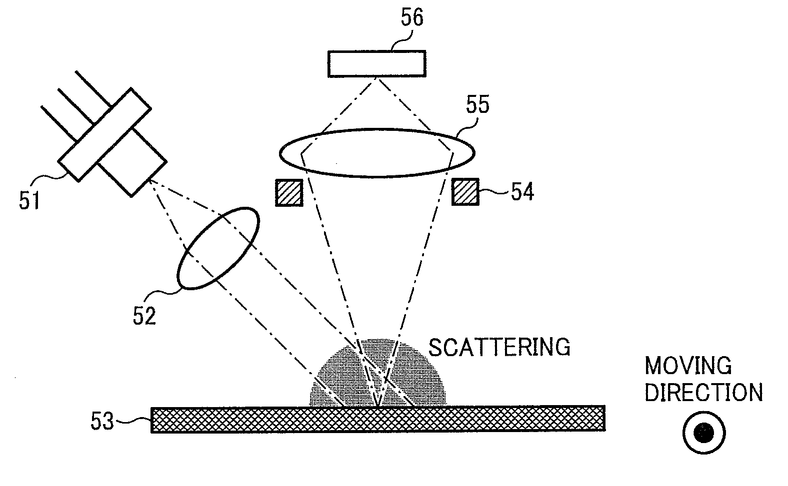
[0049]A basic configuration example of the velocity detecting device according to the present invention is shown in FIG. 3. The velocity detecting device detects velocity and velocity fluctuation of a moving member (an endless belt-like member such as an intermediate transfer belt and a conveyor belt, or a drum-like member) 53, and includes a laser light source 51 for emitting a laser light (laser beam), a collimate lens 52 for forming the laser light emitted from the laser light source 51 into nearly parallel light, an area sensor 56 that can acquire a one-dimensional or a two-dimensional image, and a lens 55 and an aperture 54 which are provided between the moving member 53 and the area sensor 56.

[0050]The laser light emitted from the laser light source 51 and formed into the nearly parallel light by the collimate lens 52 is obliquely irradiated to the moving member 53, and the moving member 53 is photographed by the one-dimensional or the two-dimensional area sensor 56 from the d...


PUM


Abstract

A velocity detecting device includes an image-pattern acquiring unit that includes a laser light source and an area sensor that acquires a one-dimensional or a two-dimensional image. The image-pattern acquiring unit includes a lens between a moving member and the area sensor, irradiates a beam emitted from the laser light source to the moving member to make a scattering light of the moving member scattered from the moving member on the area sensor by using the lens, and acquires an image pattern at a predetermined time interval in association with movement of the moving member. A velocity calculating unit calculates the velocity of the moving member by computing the image pattern acquired by the image-pattern acquiring unit. The lens is a reduced optical system that projects a reduced object onto the area sensor.

Description

CROSS-REFERENCE TO RELATED APPLICATIONS[0001]The present document incorporates by reference the entire contents of Japanese priority Patent Application No. 2009-137902 filed in Japan on Jun. 9, 2009. The present document incorporates by reference the entire contents of Japanese Application No. 2008-199273 filed in Japan on Aug. 1, 2008.BACKGROUND OF THE INVENTION[0002]1. Field of the Invention[0003]The present invention relates to a multi-color image forming apparatus for use in a digital copier, a laser printer, a laser plotter, a laser facsimile, or in a multifunction product of these units, and more particularly, to a velocity detecting device that detects velocity of an intermediate transfer belt or of a conveyor belt, and a multi-color image forming apparatus, provided with the velocity detecting device, which employs an intermediate transfer system or a direct transfer system.[0004]2. Description of the Related Art[0005]In recent color image forming apparatuses, to meet a requ...

Claims


Application Information

Patent Timeline
Patent Type & Authority Applications(United States)
IPC IPC(8): G03G15/01G06K9/00
CPCG01P3/68G01P3/806G01S17/58G03G2215/00645G03G15/0194G03G2215/0141G03G2215/0196G03G15/011G03G2215/0129
Inventor FUNATO, HIROYOSHIIMAI, SHIGEAKIMASUDA, KOJISUZUKI, HIDEMASA
Owner RICOH KK
Why Eureka
Try Eureka