
Spine formation device, post-processing apparatus, spine formation system, and spine formation method

Active Publication Date: 2010-12-09
RICOH KK
View PDF26 Cites 30 Cited by
  • Summary
  • Abstract
  • Description
  • Claims
  • Application Information

AI Technical Summary

Benefits of technology

[0015]In view of the foregoing, a purpose of the present invention is to flatten the spine of booklets with the bulging of the booklet reduced in a shorter time period while preventing the booklet from wrinkling and being torn.

Problems solved by technology

However, when a bundle of sheets (hereinafter “booklet”) is saddle-stitched or saddle-stapled and then folded in two, its folded portion, that is, a portion around its spine, tends to bulge, degrading the overall appearance of the booklet.
Consequently, the booklets might fall over when piled together.
This flattening is important for ease of storage and transport because it is difficult to stack booklets together if their spines bulge, making it difficult to store or carry them.
Although this approach can flatten the spine of the booklet to a certain extent, it is possible that the sheets might wrinkle and be torn around the spine or folded portion because the pressure roller applies localized pressure to the spine continuously.
Further, it takes longer to flatten the spine because the pressure roller moves over the entire length of the spine of the booklet.
Moreover, because only the bulging portion is pressed with the spine-forming roller in this approach, the booklet can wrinkle in a direction perpendicular to the longitudinal direction in which the spine extends, degrading its appearance.
In addition, with larger sheet sizes, productivity decreases because it takes longer for the spine-forming roller to move over the entire length of the spine of the booklet.
Although this approach can reduce, in spine formation, wrinkles of and damage to the booklet caused by the first method described above, the processing time can be still relatively long because the sandwiching member and the pressure member are operated sequentially after the booklet is pressed against the spine pressing plate.
In addition, the device is bulky because a motor is necessary to move the spine pressing plate in a reverse direction of the sheet conveyance direction.
Further, a relatively large driving force is necessary because the pressing member squeezes the booklet in a relatively small area between the spine pressing plate and the sandwiching member while the folded portion of the booklet is pressed against the spine pressing plate, increasing the power consumption, which is not desirable.

Method used


Image

  • Spine formation device, post-processing apparatus, spine formation system, and spine formation method
  • Spine formation device, post-processing apparatus, spine formation system, and spine formation method
  • Spine formation device, post-processing apparatus, spine formation system, and spine formation method

Examples


Embodiment Construction

[0042]In describing preferred embodiments illustrated in the drawings, specific terminology is employed for the sake of clarity. However, the disclosure of this patent specification is not intended to be limited to the specific terminology so selected, and it is to be understood that each specific element includes all technical equivalents that operate in a similar manner and achieve a similar result.

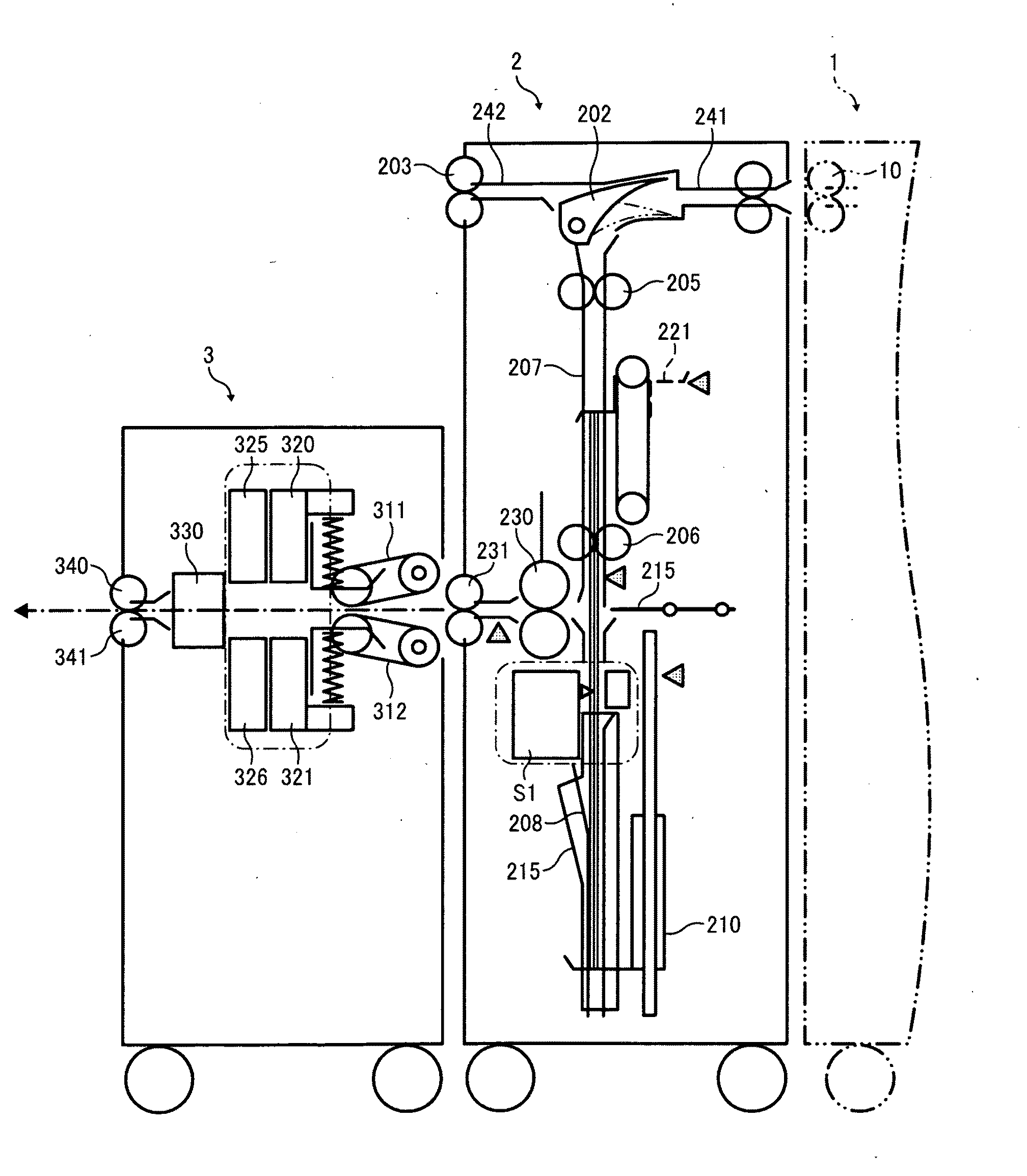
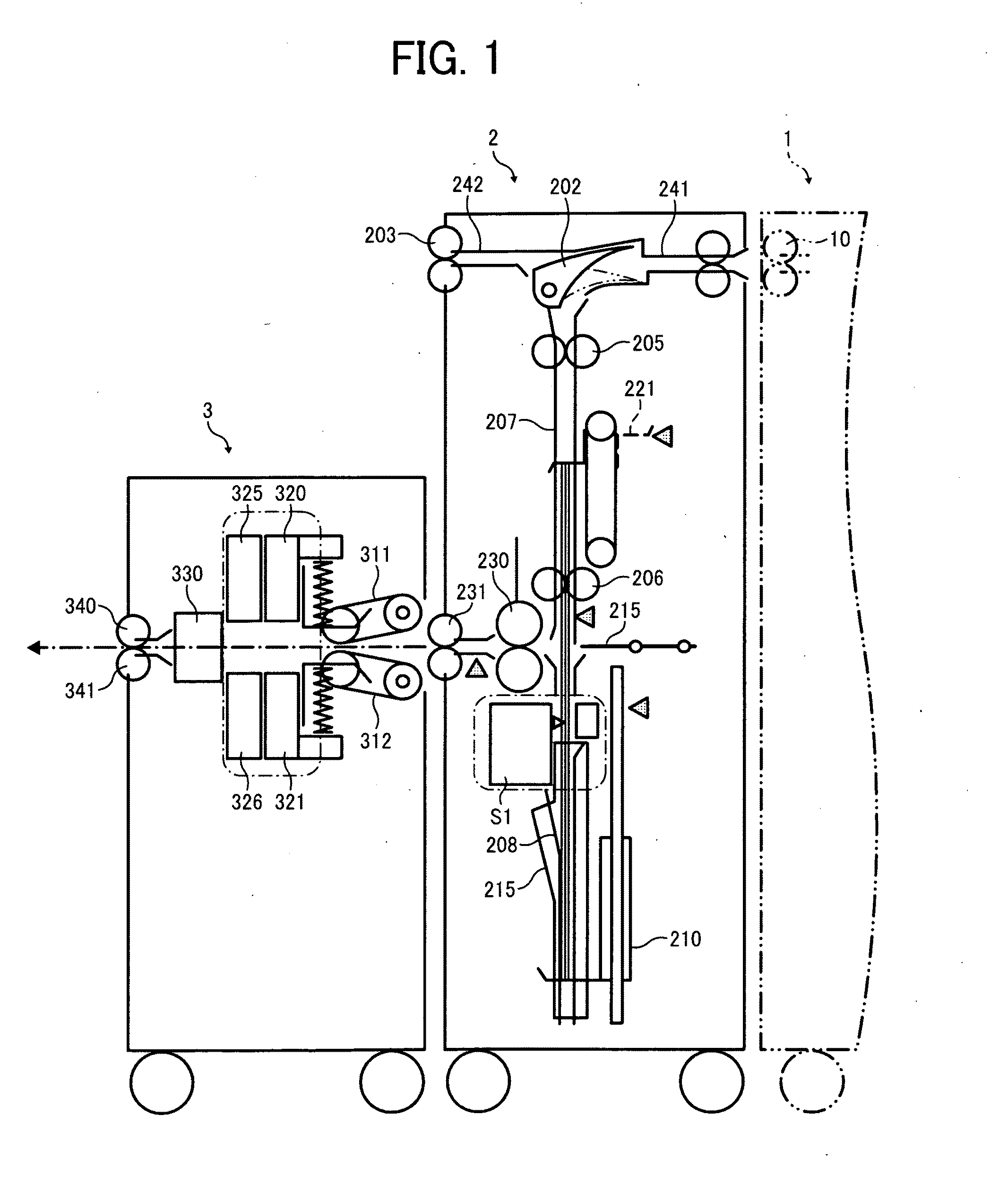
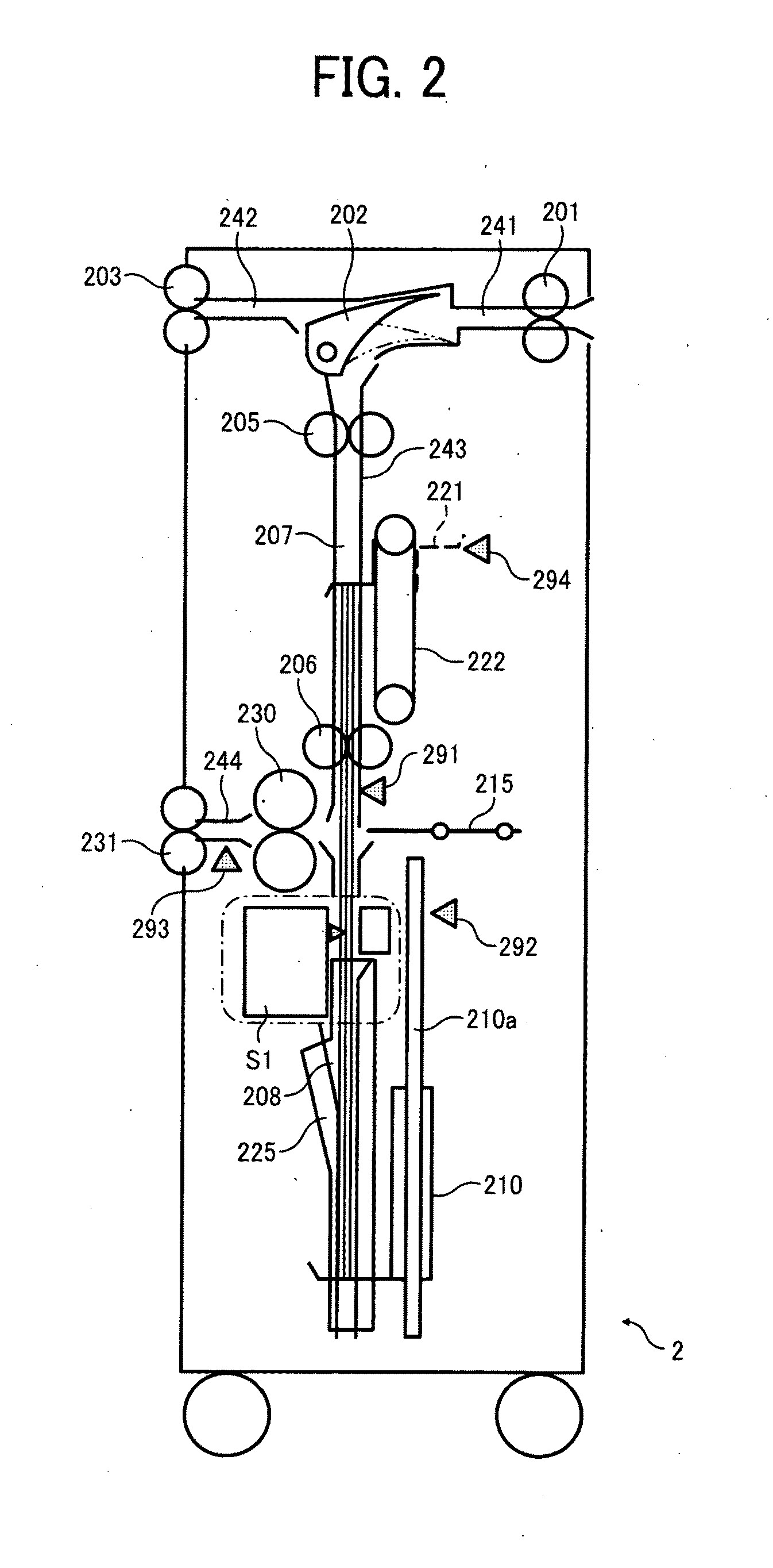
[0043]Referring now to the drawings, wherein like reference numerals designate identical or corresponding parts throughout the several views thereof, and particularly to FIG. 1, a spine formation system according to an illustrative embodiment of the present invention is described.

[0044]It is to be noted that, in the description below, a pair of transport belts 311 and 312 of a transport unit 31 serve as a sheet conveyer, a contact plate 330 serve as a contact member, a pair of auxiliary sandwiching plates 320 and 321 serve as a first sandwiching unit, a pair of sandwiching plates 325 an...


PUM

PropertyMeasurementUnit
Thicknessaaaaaaaaaa
Distanceaaaaaaaaaa

Abstract

An spine formation device includes a sheet conveyer that conveys the bundle of folded sheets in a sheet conveyance direction with a folded portion of the bundle forming front end portion thereof, first and second sandwiching units disposed downstream from the sheet conveyer, a contact member disposed downstream from the second sandwiching unit, against which the folded portion of a bundle of folded sheets is pressed, and a controller. The controller stops the sheet conveyer after the bundle is transported a predetermined distance from a contact position between the contact member and the folded portion of the bundle, causing the bundle to bulge, and causes the first and second sandwiching units to squeeze the bulging of the bundle of folded sheets in a thickness direction sequentially with the folded portion of the bundle pressed against the contact member to form a spine of the bundle.

Description

CROSS-REFERENCE TO RELATED APPLICATIONS[0001]This patent specification is based on and claims priority from Japanese Patent Application Nos. 2009-138515, filed on Jun. 9, 2009, and 2010-012267, filed on Jan. 22, 2010, in the Japan Patent Office, the contents of which are hereby incorporated by reference herein in their entirety.BACKGROUND OF THE INVENTION[0002]1. Field of the Invention[0003]The present invention generally relates to a spine formation device to form a spine of a bundle of folded sheets, a post-processing apparatus including the spine formation device, and a spine formation system including the spine formation device and an image forming apparatus, and a method of forming a spine of a booklet.[0004]2. Discussion of the Background Art[0005]Post-processing apparatuses to perform post processing of recording media, such as aligning, sorting, stapling, punching, and folding of sheets, are widely used and are often disposed downstream from an image forming apparatus to per...

Claims


Application Information

Patent Timeline
IPC IPC(8): B42B5/00
CPCB65H45/18B65H2801/27B65H2701/13212
Inventor SUZUKI, NOBUYOSHIASAMI, SHINJIKIKKAWA, NAOHIRO
Owner RICOH KK
Learn More