Abutment with inlay for dental implants

a technology of inlay and dental implants, applied in dental prosthetics, dentistry, medical science, etc., can solve the problems of reducing overall stability, risk of loosening of the material bond between the inlay material and the inlay, and shape must be reworked at high cost or a new abutment must be produced, so as to achieve the effect of better adhesion of the inlay

Inactive Publication Date: 2010-12-09
STRAUMANN HLDG AG
View PDF49 Cites 12 Cited by
  • Summary
  • Abstract
  • Description
  • Claims
  • Application Information

AI Technical Summary

Benefits of technology

[0012]It is therefore an object of the present invention to find a solutio

Problems solved by technology

The disadvantage of a modeling method, however, is that each molded model is unique, and if errors occur e. g. during manufacturing, the shape must be reworked at high cost or a new abutment must be produced.
The shoulder portions protrude from the abutment's surface, and the relatively small area of the supporting surface in this region for an abutment formed thereon entails the danger of loosening of the material bond between the inlay material and the abutment material, either due to material fatigue or due to the forces exerted during chewing.
This can lead to the trapping of air between the inner abutment surface and the outer inlay surface, causing a reduction in overall stability due to the inhomogeneous distribution of the formed parts.
This connection achieves stability and stiffening of the dental implant system; however, there is no anti-rotational securing in the apical portion where the abutment is formed to the inlay.
T

Method used


Image

  • Abutment with inlay for dental implants
  • Abutment with inlay for dental implants
  • Abutment with inlay for dental implants

Examples


Embodiment Construction

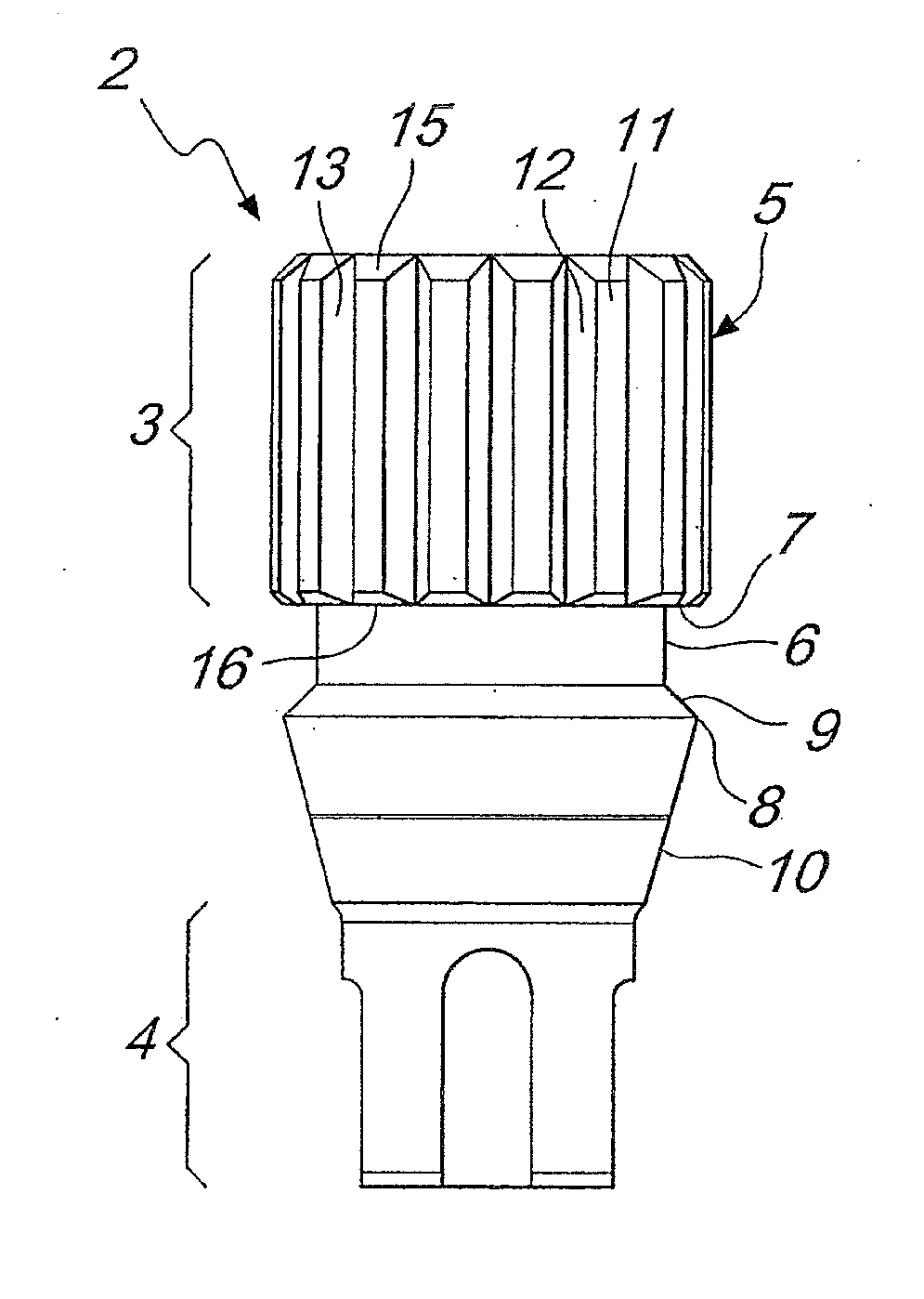
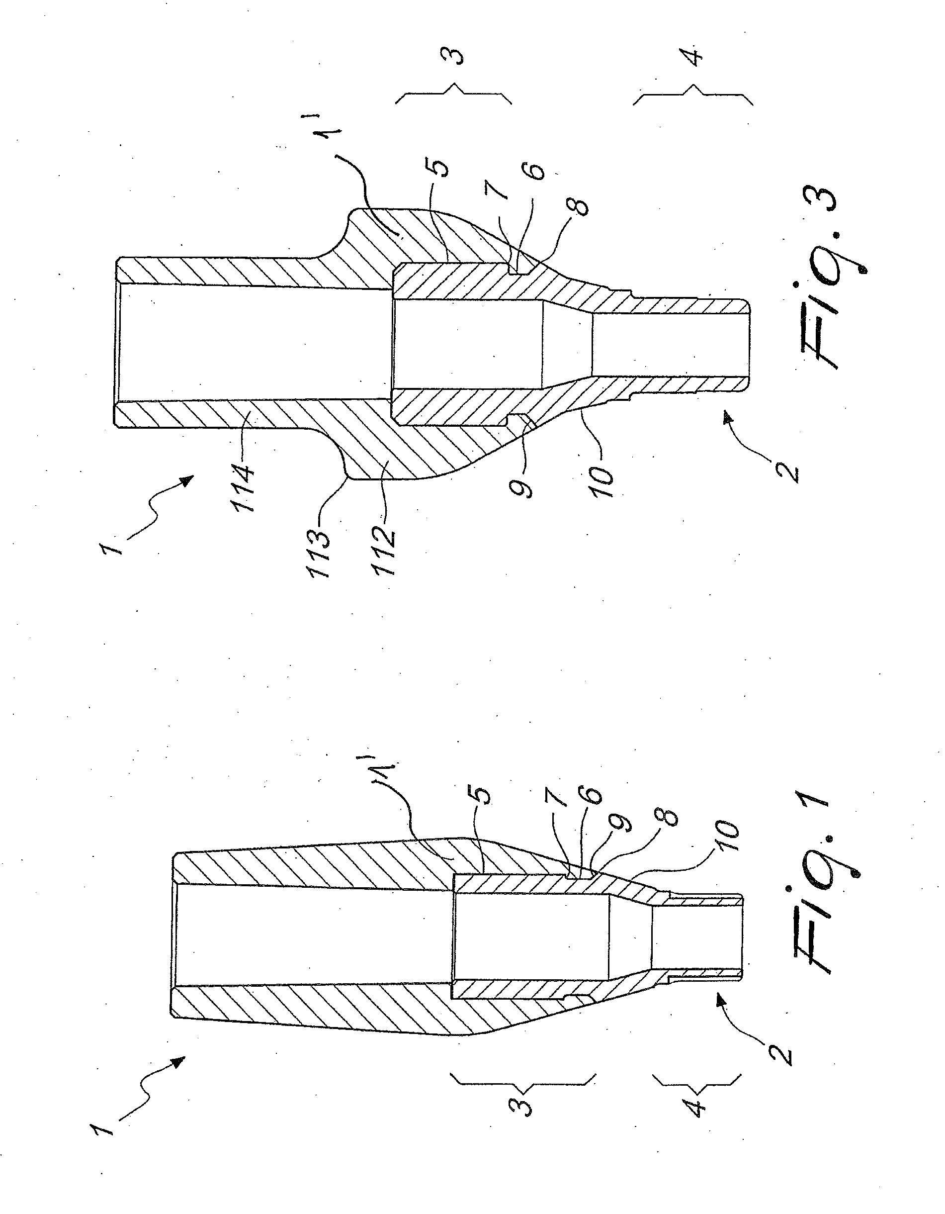
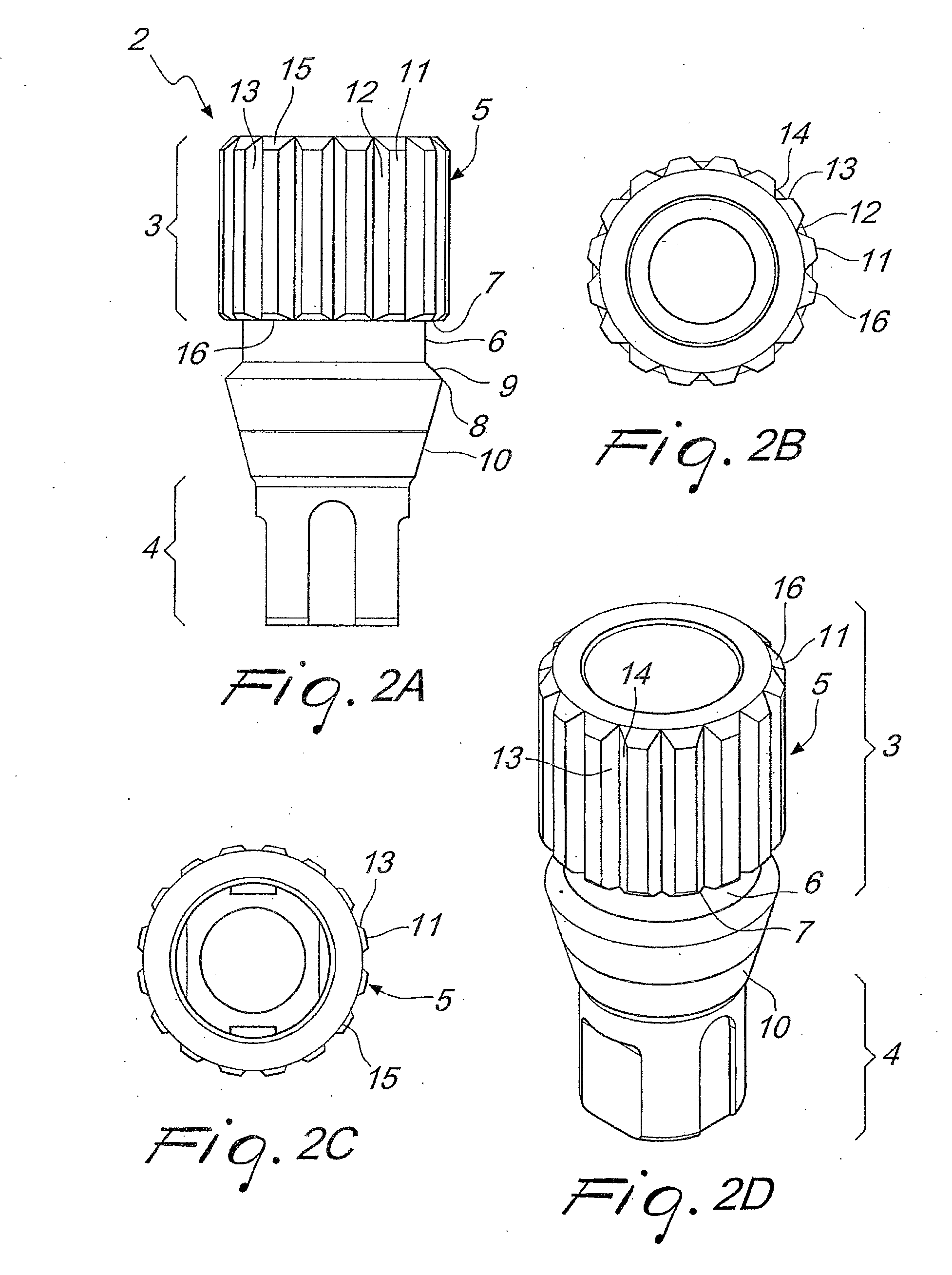
[0027]With reference to FIG. 1, a currently preferred embodiment of an abutment with inlay according to the present invention is described, which abutment is generally designated by reference number 1. An abutment with inlay for provision of a dental implant, which as such is sufficiently known and therefore not described further, comprises an exterior abutment portion 1′ within which an inlay 2 is arranged apically.

[0028]The inlay 2 coronally has an outer portion 3 which is suitable to provide a connection between the inlay 2 and the outer abutment portion 1′ and an apical portion 4 which is suitable for releasable connection to a dental implant.

[0029]The surface 5 of the coronal portion 3 of the inlay 2 is shaped such that an outer abutment part 1′ can positively engage it and be connected to it practically in a non-detachable manner. In positive engagement, an outer abutment part 1′ manufactured previously is simply pressed onto the coronal portion 3 of the inlay 2. Alternatively...


PUM


Abstract

The invention relates to an abutment with inlay for dental implants, comprising an outer abutment part and an inlay, which is disposed apically within the outer abutment part. The inlay has a coronal section, which is suitable for producing a connection between the inlay and the outer abutment part, and an apical region, which is suitable for the detachable connection with a dental implant. The invention wherein the surface of the coronal section of the inlay is constructed in order to positively connect the outer abutment part, which is to be mounted undetachably thereon.

Description

FIELD OF USE OF THE INVENTION [0001]The present invention generally refers to an abutment with inlay, for establishing a connection between a dental implant and an abutment, particularly for screw- or cylinder-shaped dental implants, wherein the abutment having an inlay proves for anti-rotational securing and allows an easy assembly of the fabricated individual denture.PRIOR ART [0002]An abutment is generally fastened on a dental implant, which is sufficiently known in the art and which is inserted in the jaw bone of a patient, the abutment being either a permanent or a temporary element. To achieve good fixation and reinforcement of the abutment, an intermediate element called inlay is inserted in the abutment in the direction of the dental implant. The abutment can be inserted both temporarily, e. g. during the healing process of a dental implant, or permanently, at the end of treatment, for providing a denture modeled on the abutment.[0003]The inlay generally consists of a high-s...

Claims


Application Information

Patent Timeline
IPC IPC(8): A61C13/225
CPCA61C8/005
Inventor SCHWIEDER, FABIANGUENTER, DANIEL
Owner STRAUMANN HLDG AG
Why Eureka
Try Eureka