

Systems for intraoperative nerve imaging
a nerve imaging and system technology, applied in the field of systems, can solve the problems of low light sensitivity of imaging instruments, many technical challenges, and insufficient light attenuation of tissue, and achieve the effect of high collection power
- Summary
- Abstract
- Description
- Claims
- Application Information
AI Technical Summary
Benefits of technology
Problems solved by technology
Method used
Image

Examples
Embodiment Construction
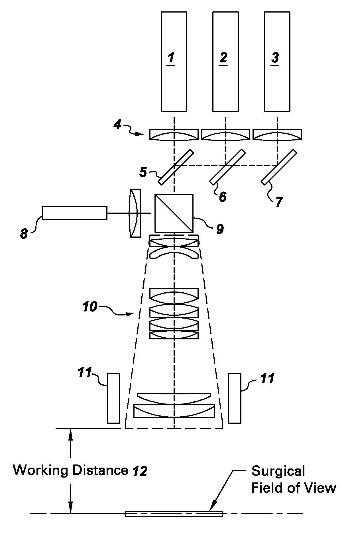
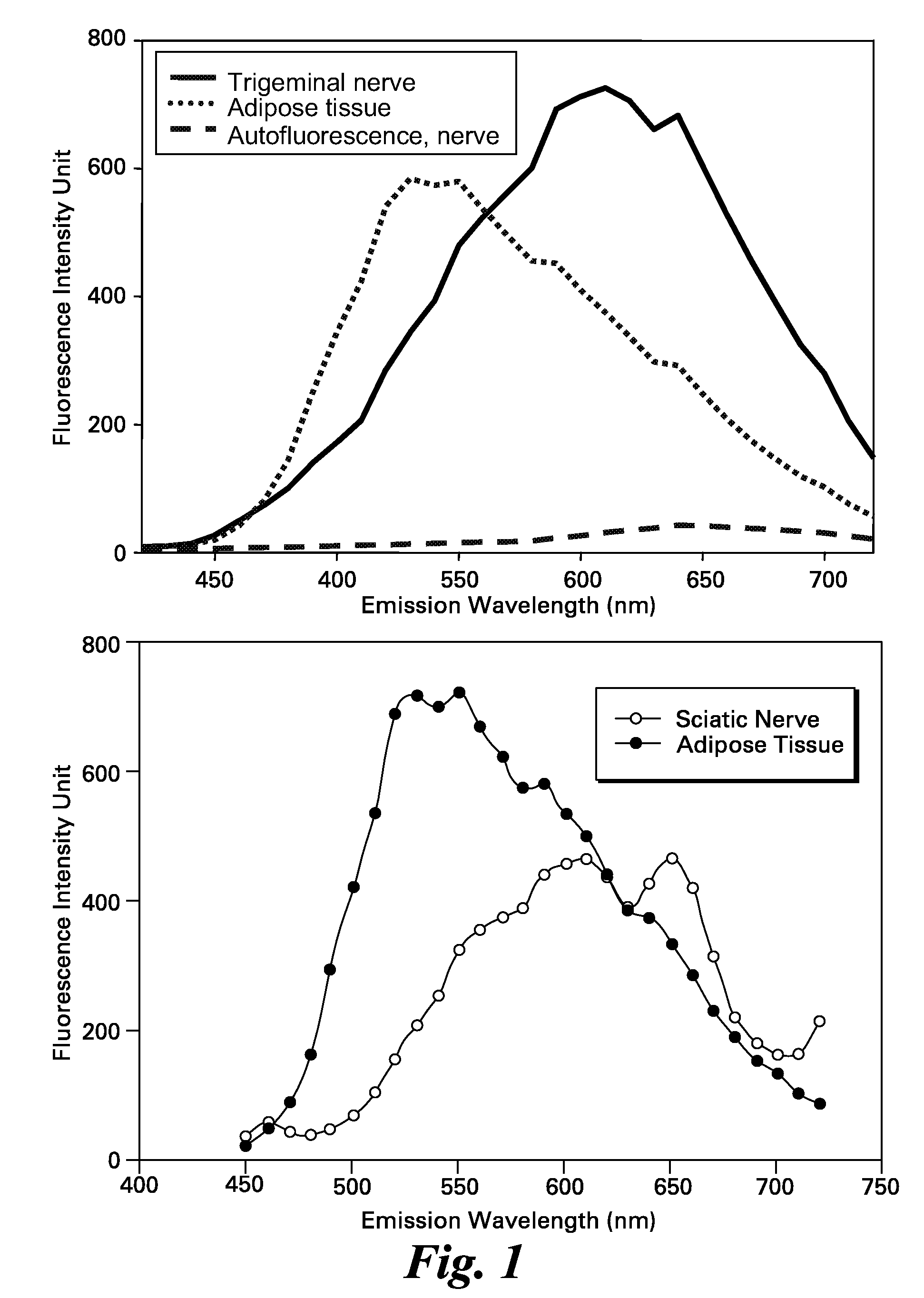
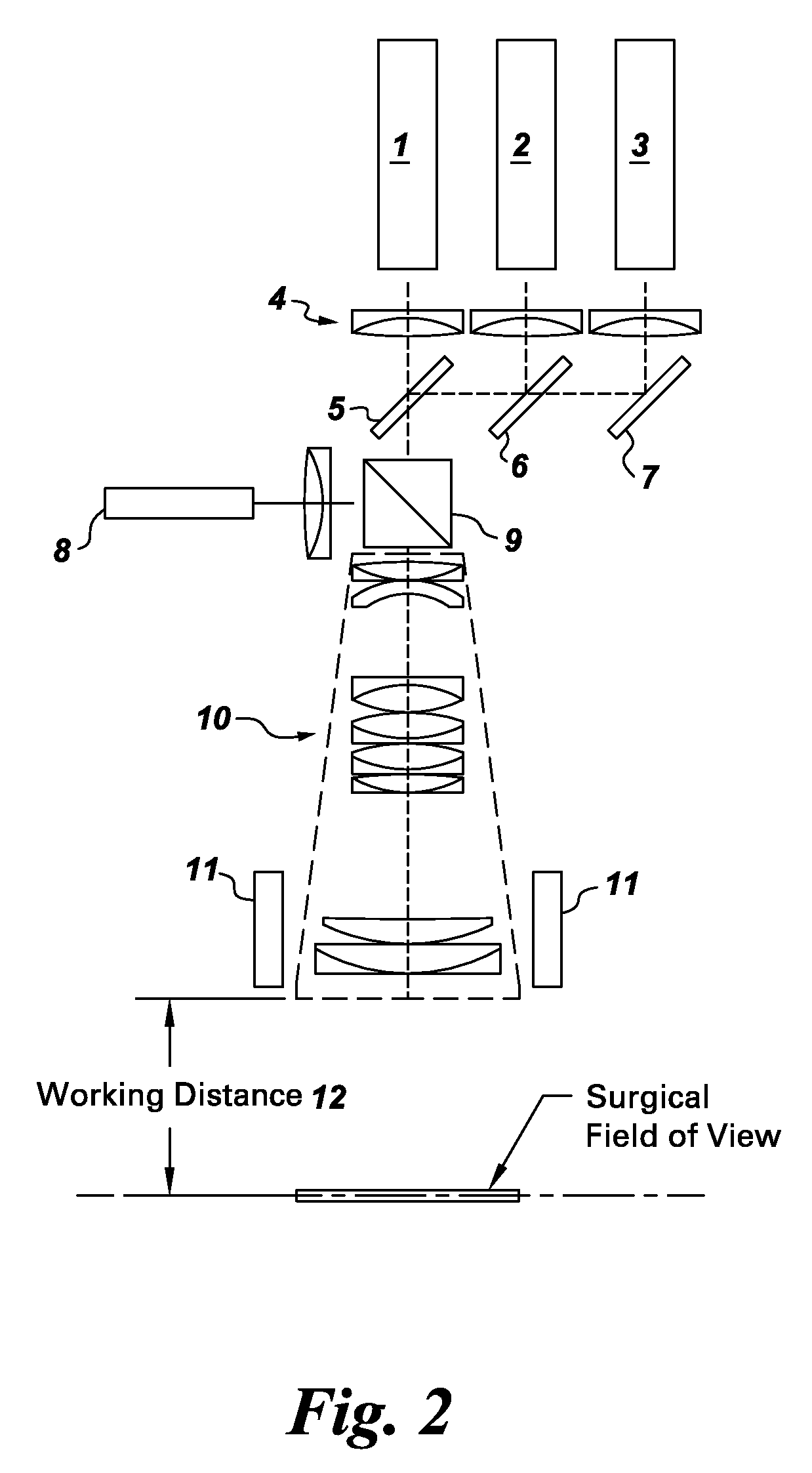
[0021]Embodiments of the invention relate to a compact dual fluorescence imaging system for open and minimally invasive surgical procedures. Iatrogenic nerve damage can be reduced in cardiovascular and breast cancer surgeries, both of which are predominantly performed as open surgeries, i.e., via large open incisions. For cardiovascular applications such as coronary artery bypass graft surgery (CABG), there is a need to simultaneously visualize the vasculature and the nerves. A precedent exists for using indocyanine green as a blood pool agent. In breast cancer, there is a need to increase contrast, which suffers from partitioning of the agent to adipose tissue. In applications wherein the emission spectrum of the fluorophore is sensitive to the environment ratiometric imaging may discriminate nerve from adipose tissue signal.
[0022]A targeted nerve imaging agent for fluorescence guided surgical imaging of nerves must nominally feature several attributes: the ability to penetrate the...
PUM
 Abstract
Description
Claims
Application Information