
Objective for optical imaging systems

Active Publication Date: 2011-02-08
GENERAL ELECTRIC CO
View PDF25 Cites 4 Cited by
  • Summary
  • Abstract
  • Description
  • Claims
  • Application Information

AI Technical Summary

Benefits of technology

[0009]It is therefore desirable to provide a compact endoscope obj

Problems solved by technology

However, many technical challenges are still present.
One of the challenges is the specificity and affinity of the contrast agent.
With respect to the physics of imaging, a challenge is light attenuation in living tissue.
Yet another challenge is the sensitivity of the imaging instrument at low light conditions.
For example, during cholecystectomy, an uncommon but potentially serious complication with the procedure is injury to the common bile duct.
At 25-100 mm working distance, the NA may be on the order of 0.002-0.008, resulting in low collection power.
On the detector side, the majority of video endoscopes use ¼ inch or ⅙ inch detectors, which have small pixels, resulting in very low sensitivity.
Although this is normally adequate for white light imaging, it is not optimized for fluorescence imaging, where the typical fluorescence signal strength from stained tissue is substantially weaker than the white light reflectance image.

Method used


Image

  • Objective for optical imaging systems
  • Objective for optical imaging systems
  • Objective for optical imaging systems

Examples


Embodiment Construction

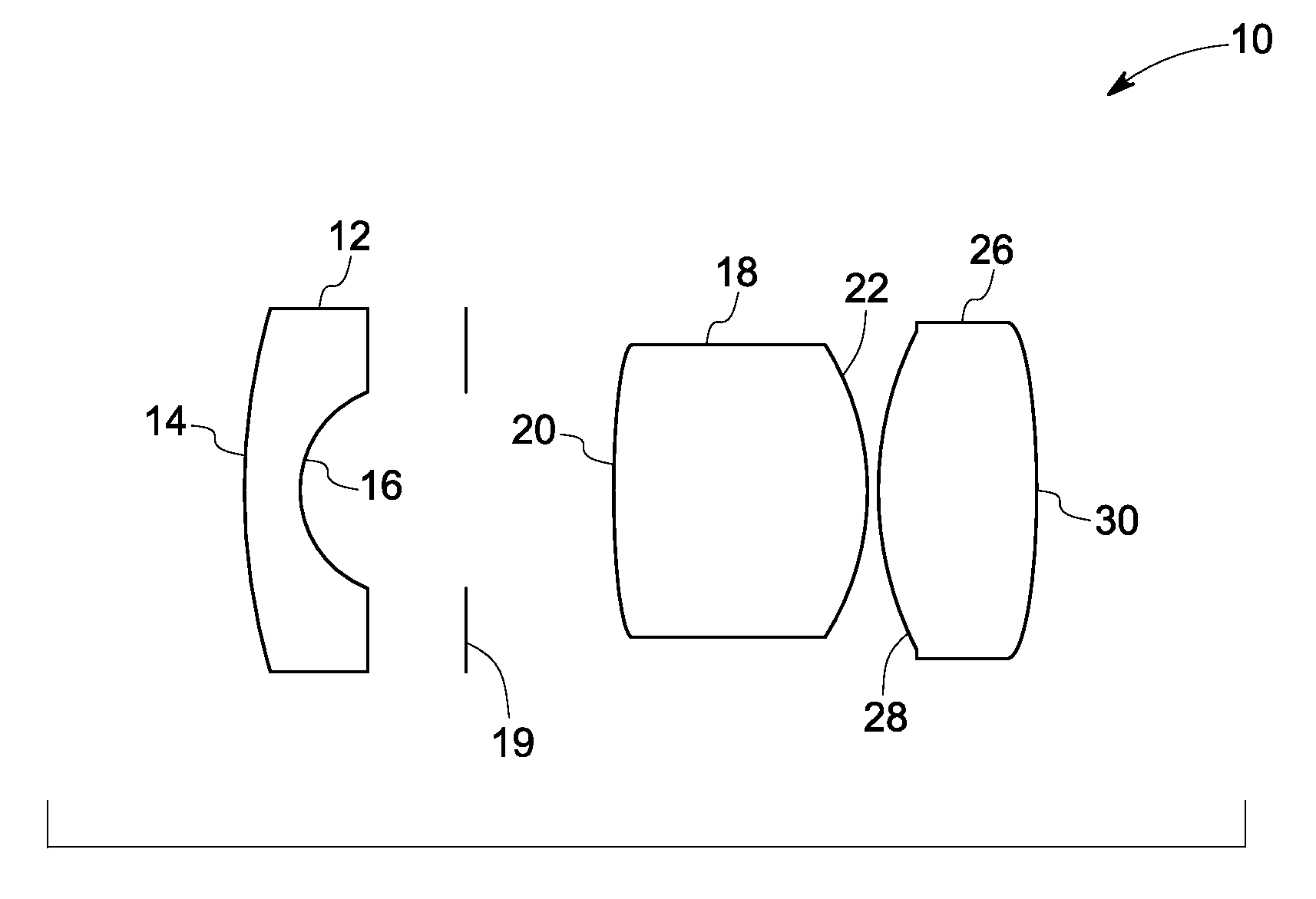
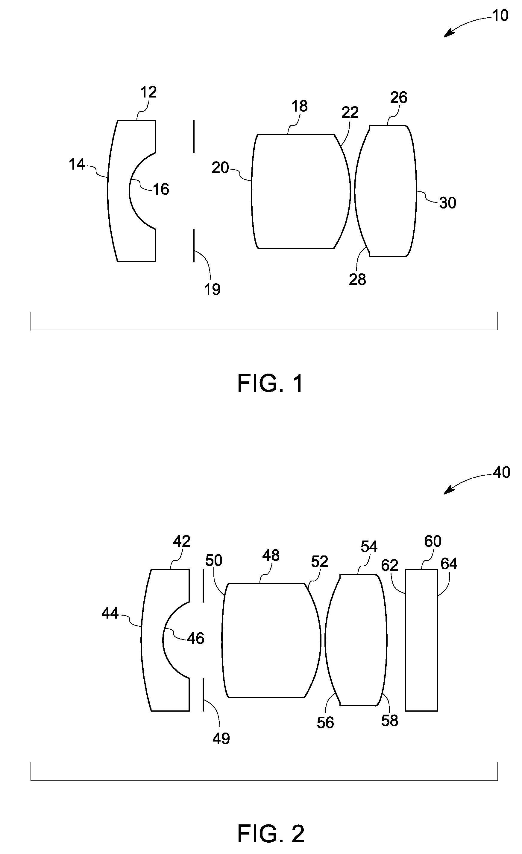
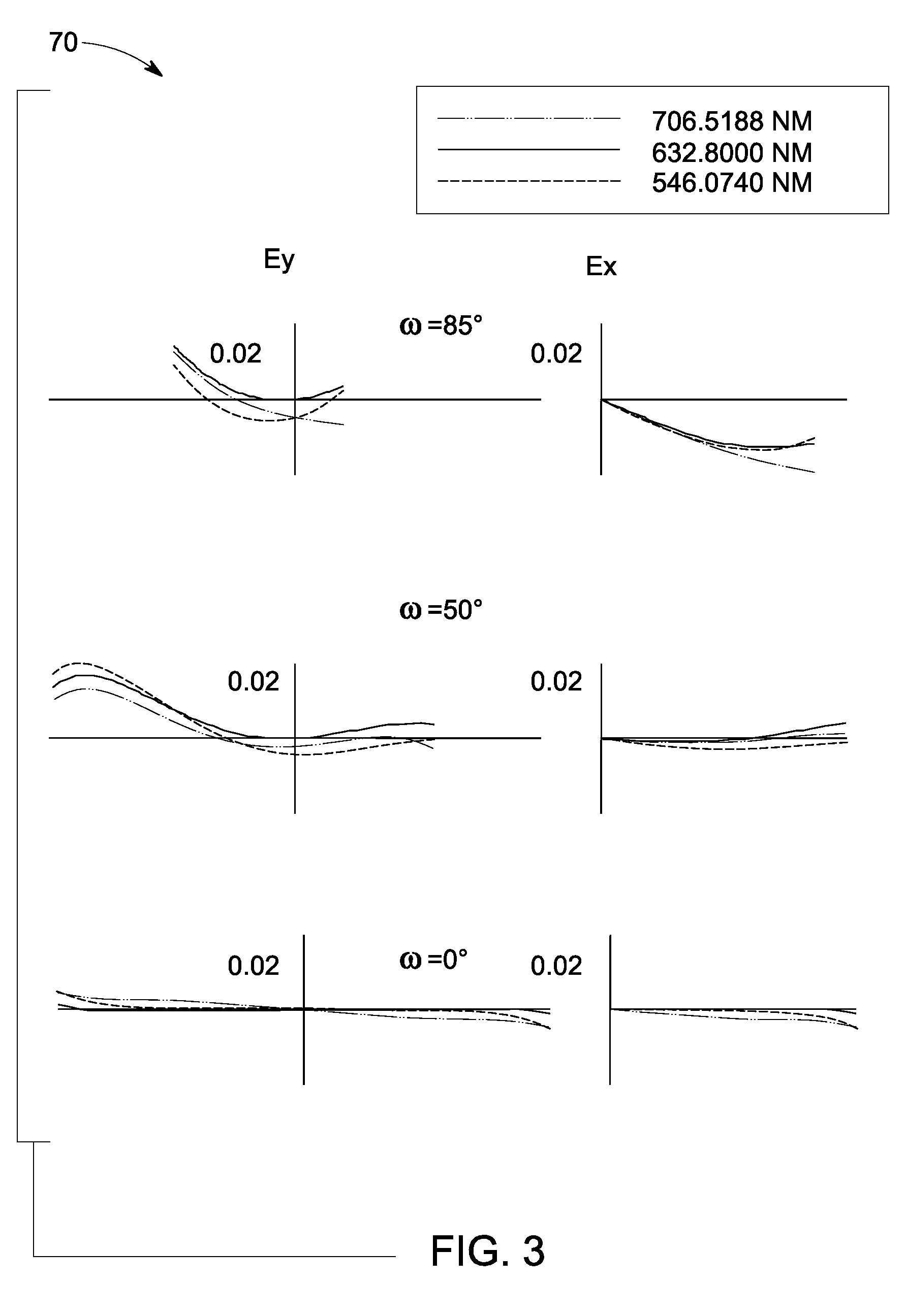
[0019]Embodiments of the invention relate to a wide angle hybrid refractive-diffractive endoscope objective for optical imaging systems. In certain embodiments, a hybrid refractive-diffractive element is employed to increase the entrance pupil diameter (EPD) of a wide angle fisheye lens, thus achieving higher collection power and maintaining small overall diameter. The entrance pupil diameter (EPD) of the objective may be greater than about 0.6 mm. As used herein the term “entrance pupil diameter” means the diameter of a virtual aperture that defines the area at the entrance of the optical system that can accept light rays, such that the rays that pass through the pupil are able to enter the optical system and pass through the optical system through the exit. Collection power of a lens is proportional to the square of the EPD, therefore, the objective of the invention has about 9 to 25 times higher collection power than conventional endoscope objectives which have EPD of about 0.2 m...


PUM


Abstract

A wide angle hybrid refractive-diffractive endoscope objective is provided. The objective comprises a negative meniscus lens having a first surface and a second surface; a stop adjacent to the negative meniscus lens; a positive lens adjacent to the negative lens and having a first surface and a second surface; and a hybrid refractive-diffractive element adjacent to the positive lens and having a first surface and a second surface, wherein one of the first surface, or the second surface comprises a diffractive surface, wherein the objective has an effective focal length in a range from about 0.8 mm to about 1.6 mm.

Description

BACKGROUND[0001]The invention relates generally to the field of endoscopic imaging and more specifically, to the field of optical design of compact high collection power endoscopic objectives for fluorescence and white light imaging.[0002]Fluorescence imaging is used to highlight molecules and structures not otherwise visible under white light illumination. By administering a molecular contrast agent to a patient, disease processes can be specifically labeled for visualization during clinical examination. In concert with white light imaging, fluorescence imaging captures movies of anatomy with tissue specific information, and provides the clinician with a macroscopic visualization of biology in its intact and native physiological state. It holds promise as a way for real time guidance for tumor resection, sentinel lymph node mapping, vasculature and tissue perfusion imaging, as well as early detection of colorectal cancer.[0003]However, many technical challenges are still present. O...

Claims


Application Information

Patent Timeline
IPC IPC(8): G02B21/02G02B13/18
CPCG02B23/243
Inventor WANG, XINGHUAMEYERS, MARK MARSHALLYAZDANFAR, SIAVASH
Owner GENERAL ELECTRIC CO
Learn More