Chemical Injection System

a chemical injection and system technology, applied in the direction of sealing/packing, instruments, borehole/well accessories, etc., can solve the problems of not being able to communicate with other the chemical injector may not be able to communicate with equipment and/or monitoring systems communicably coupled with the chemical injector, and the need for increasing the set amount of additives

Inactive Publication Date: 2010-12-09
DRESSER IND INC
View PDF50 Cites 22 Cited by
  • Summary
  • Abstract
  • Description
  • Claims
  • Application Information

AI Technical Summary

Benefits of technology

[0022]In one aspect of one or more general embodiments, the translator may be adapted to receive the second signal from the receiver, the second signal in the second communication protocol, and translate the second signal to a third signal in the first communication protocol.
[0023]In one aspect of one or more general embodiments, the second communication protocol may include a Modbus protocol.
[0024]In one aspect of one or more general embodiments, the GUI may be adapted to display one or more operational parameters of the chemical injection system.
[0025]In one aspect of one or more general embodiments, a system may further include a transceiver communicably coupled to the remote computing station through a communications network, the transceiver in RF communication with the chemical injection system.
[0026]In one aspect of one or more general embodiments, a system may further include one or more communication stations in RF communication with the chemical injection system and the transceiver, where each communication station is adapted to relay operational parameters of the chemical injection system in the form of RF signals between the transceiver and the chemical injection system.
[0027]In one aspect of one or more general embodiments, a system may further include: a second sensor coupled with the hydrocarbon transmission system; and a second chemical injection system. The second chemical injection system may include a pump in fluid communication with the chemical reservoir and the hydrocarbon transmission system; a motor coupled to the pump and adapted to drive the pump to transfer the chemical fluid from the reservoir to the hydrocarbon transmission system; a power module; a motor controller electrically coupled to the power module and the second motor and adapted to adjust a rotational speed of the motor; and a central controller communicably coupled to the motor controller and to the remote computing system and the second sensor. The controller may include a translator adapted to receive a signal from the remote computing system in the first communication protocol and translate the signal from the remote computing system to a command in the second communication protocol distinct from the first communication protocol, where the command is operable to adjust the motor controller to adjust the rotational speed of the motor.

Problems solved by technology

In such instances, however, the chemical injector may simply inject the additives on a timer system without regard to certain variables such as, for example, the flow rate through the pipeline the amount (percentage concentration) of additives already within the transported hydrocarbon fluids in the pipeline, possible problems within the pipeline or production facility, and / or a desired or required increase in the set amount of additives injected into the pipeline.
Further, the chemical injector may have no ability to communicate with other equipment and / or monitoring systems in order to take account of such variables.
If communication is possible, however, equipment and / or monitoring systems communicably coupled with the chemical injector may not transmit data and / or instructions in a protocol readily understood by the chemical injector, or vice versa.

Method used


Image

  • Chemical Injection System
  • Chemical Injection System
  • Chemical Injection System

Examples


Embodiment Construction

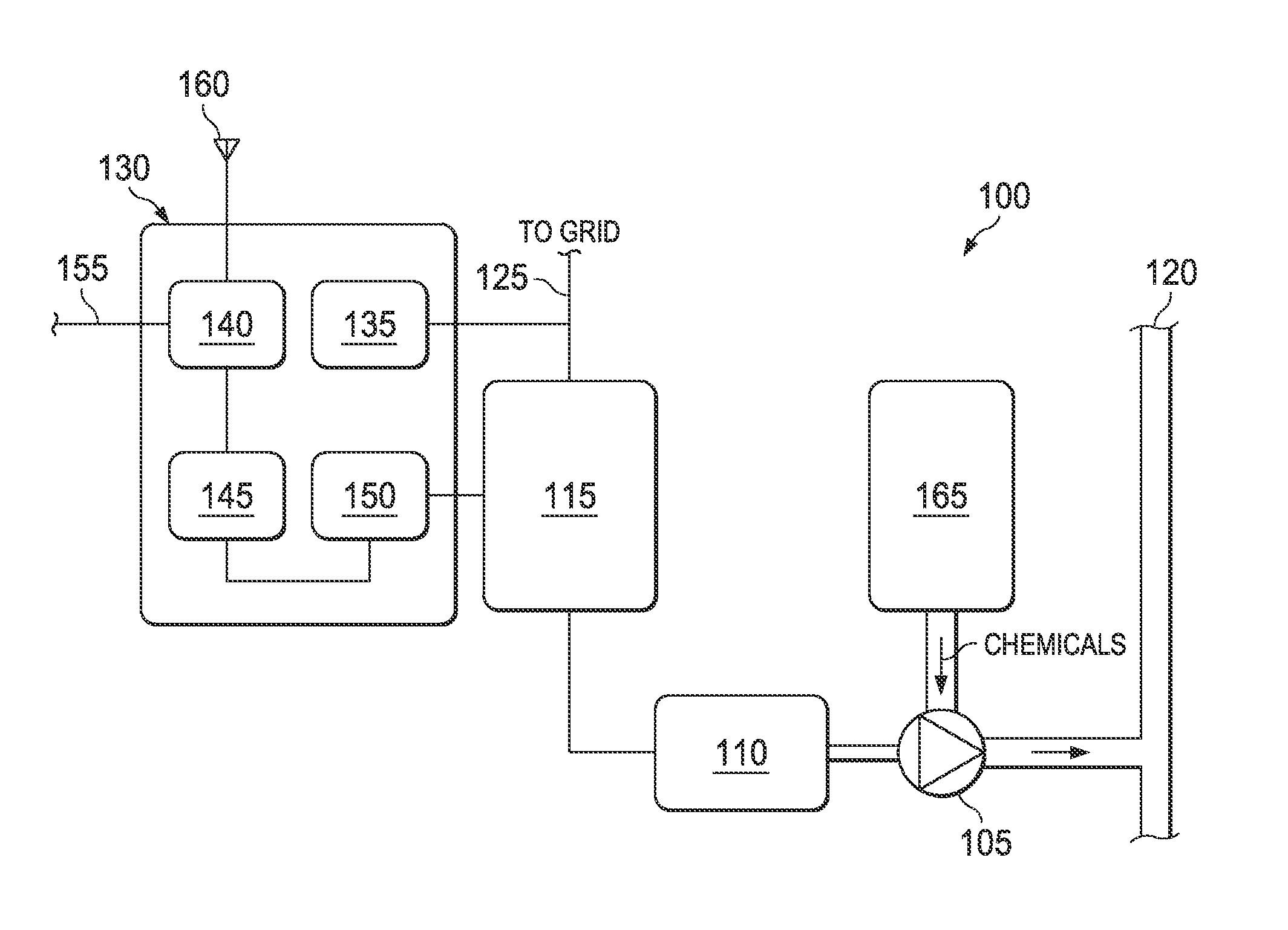
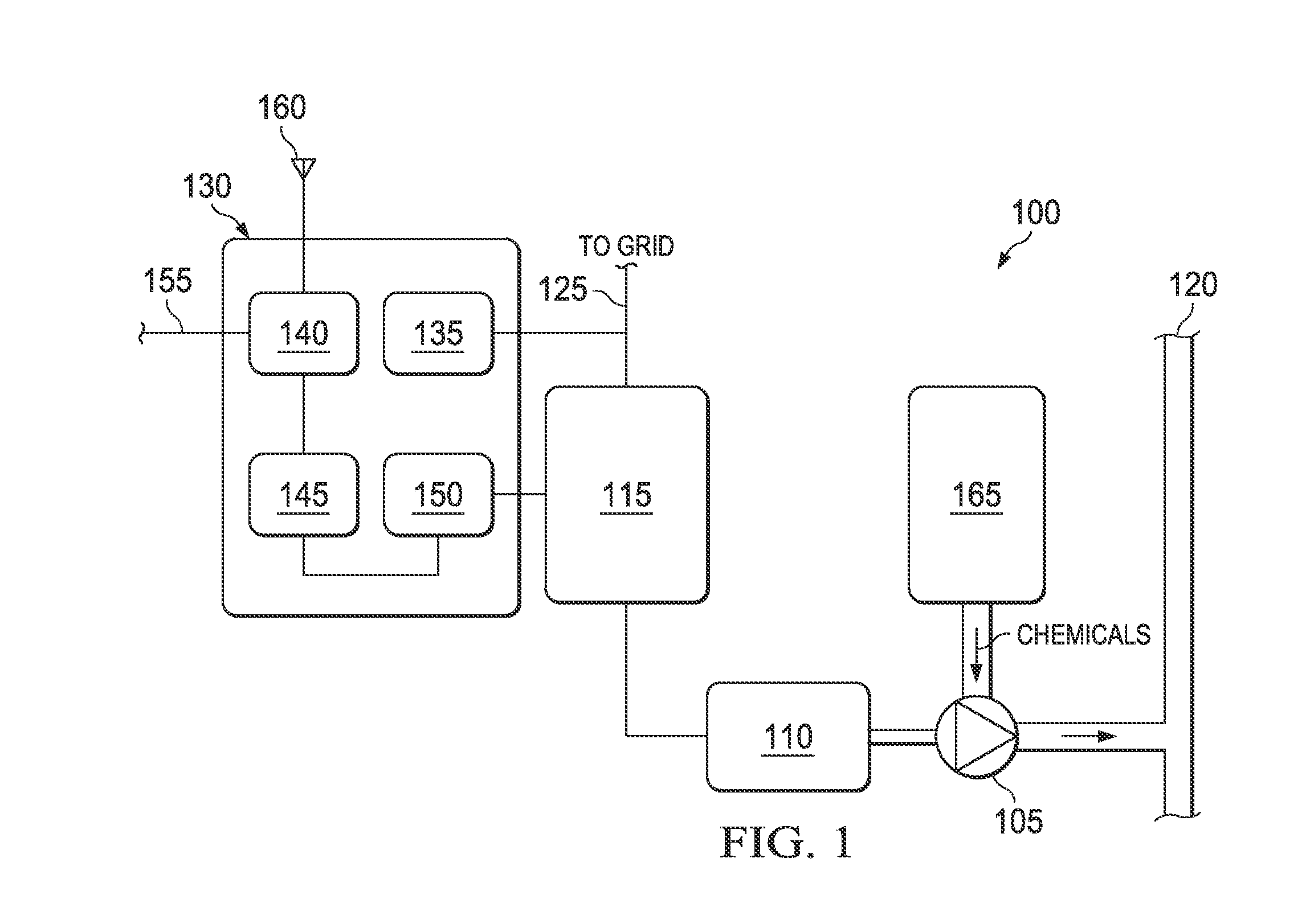
[0034]In one embodiment, a chemical injection system for a hydrocarbon transmission system includes a pumping system adapted to inject a specified amount of chemical additive into the transmission system; and a controller communicably coupled to the pumping system and adapted to receive one or more operational parameters of the transmission system and transmit a command to the pumping system based on the one or more operational parameters, where the pumping system injects the specified amount in response to the command.

[0035]In another embodiment, a chemical injection system for a hydrocarbon transmission system includes a pumping system adapted to inject a specified amount of chemical additive into the transmission system; and a controller communicably coupled to the pumping system and adapted to receive one or more operational parameters of the transmission system in a first communication protocol and transmit a command to the pumping system based on the one or more operational pa...


PUM


Abstract

A chemical injection system includes a pump in fluid communication with a chemical reservoir and a pipeline; a motor coupled to the pump and adapted to drive the pump to transfer a chemical fluid from the reservoir to the pipeline; a motor controller electrically coupled to a power module and the motor and adapted to adjust a rotational speed of the motor; and a central controller communicably coupled to the motor controller and a remote computing device. The controller includes a translator adapted to receive a signal from the remote computing device in a first communication protocol and translate the signal from the remote computing device to a command in a second communication protocol distinct from the first communication protocol, where the command is operable to adjust the motor controller to adjust the rotational speed of the motor.

Description

CLAIM OF PRIORITY[0001]This application claims priority under 35 U.S.C. §119(e) to U.S. Provisional Patent Application Ser. No. 61 / 184,890, filed on Jun. 8, 2009, the entire contents of which are hereby incorporated by reference.TECHNICAL BACKGROUND[0002]This disclosure relates to a chemical injection system and, more particularly, to a chemical injection system controlled through remote communications via one or more communication protocols.BACKGROUND[0003]Conduit systems that carry and / or transport one or more fluids may utilize injection systems to insert other fluids (e.g., additives, inhibitors, or otherwise) into the conduit system. For example, hydrocarbon systems that transport hydrocarbon fluids, such as oil and / or gas or other fluids, often receive injected fluids in order to, for example, control corrosion within the conduit or pipeline; prevent paraffin deposition; and break emulsions in the transported hydrocarbon fluids. The injected fluids may also be used for water r...

Claims


Application Information

Patent Timeline
Patent Type & Authority Applications(United States)
IPC IPC(8): G05D7/06
CPCE21B33/068G05D11/13G05D11/132G05D7/0617G05B15/02
Inventor GUTIERREZ, FRANCISCO M.ATTON, RICHARD D.
Owner DRESSER IND INC
Why Eureka
Try Eureka