System and Method for Associating Time Stamped Measurement Data with a Corresponding Wellbore Depth

Active Publication Date: 2010-12-16
SCHLUMBERGER TECH CORP
View PDF10 Cites 36 Cited by
  • Summary
  • Abstract
  • Description
  • Claims
  • Application Information

AI Technical Summary

Problems solved by technology

In addition, the internal timing mechanism of the tool may experience drift relative to the computer located at the surface such that the time indicated by the internal timing mechanism may not match the time indicated by the computer.
However, the transmission of the measurements by a relatively slower telemetry technology may be hindered by the inclusion of the time data.
Moreover, the telemetry technology may not have the capability to transmit the time data with the measurement

Method used


Image

  • System and Method for Associating Time Stamped Measurement Data with a Corresponding Wellbore Depth
  • System and Method for Associating Time Stamped Measurement Data with a Corresponding Wellbore Depth
  • System and Method for Associating Time Stamped Measurement Data with a Corresponding Wellbore Depth

Examples


Embodiment Construction

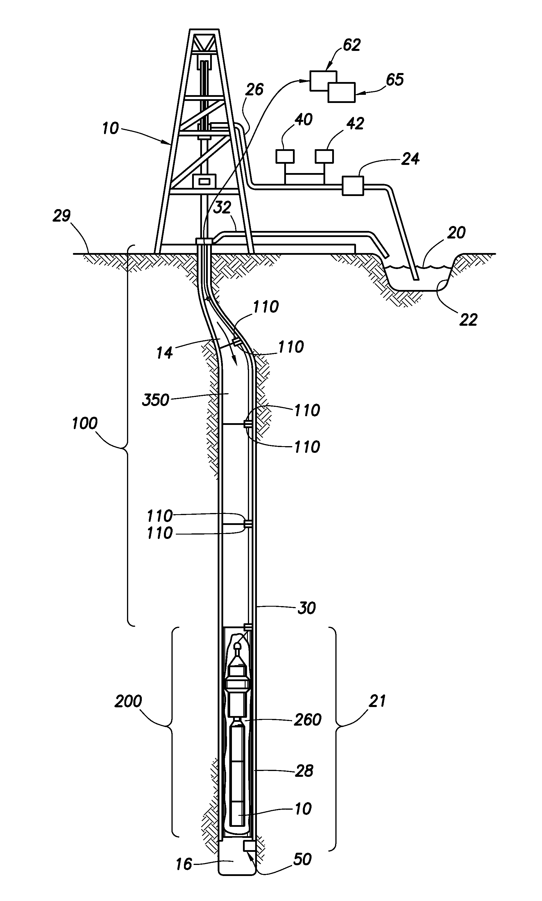
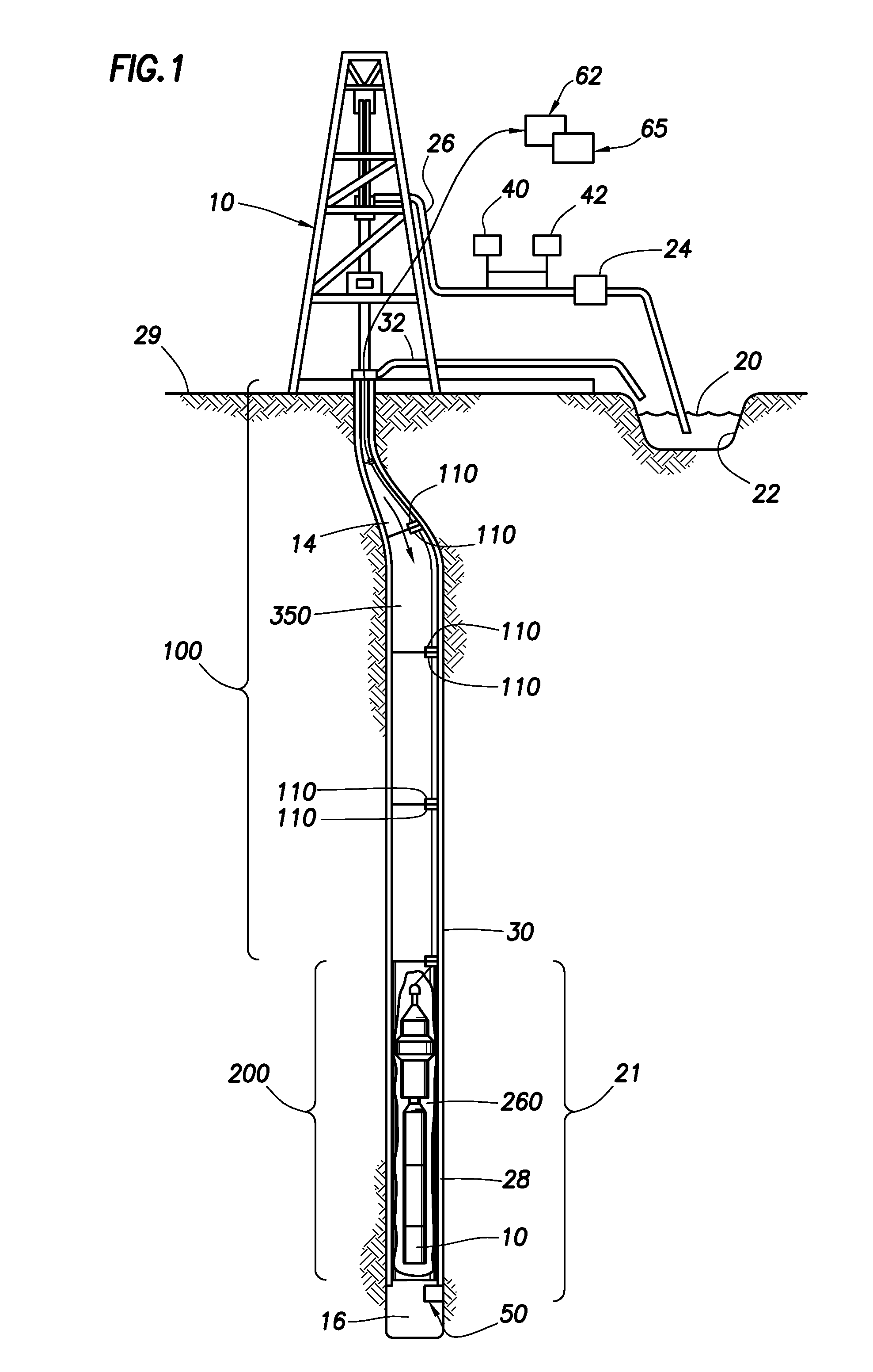
[0016]The present invention generally relates to a system and a method for associating time stamped measurement data with a corresponding wellbore depth. More specifically, the present invention relates to tools located in a wellbore that obtain the measurement data, and the measurement data is transmitted to the Earth's surface with time information. Wellbore depths may also be recorded as a function of time. As a result, the measurement data may be associated with the wellbore depth in which the measurement data was obtained based on the time information.

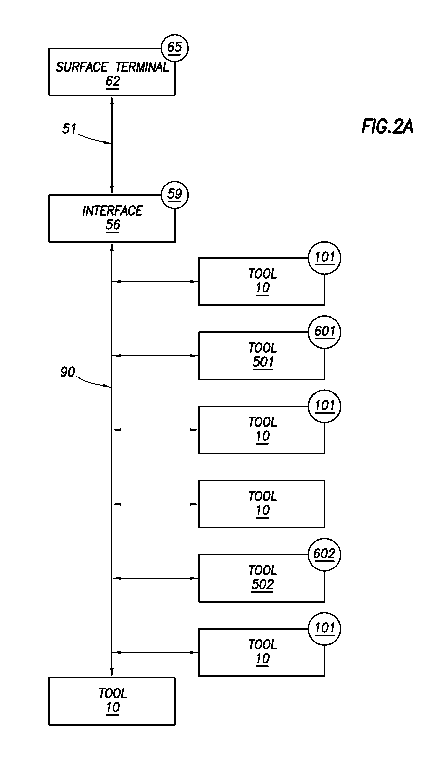
[0017]One or more of the tools may have a downhole clock and a surface terminal or other device may have a surface clock. The downhole clock and the surface clock may be synchronized. In an embodiment, the tools may determine a drift so that the tools may continue synchronization despite interruption of communication with the surface location by the telemetry system. A master tool may synchronize with a surface clock and / or may sy...


PUM


Abstract

A system and a method for associating measurements from a wellbore with times and depths is provided. Tools located in a wellbore obtain the measurements and provide time data used to determine the times. The tools and a surface clock may be synchronized. The times may be used to associate the measurements with corresponding depths of the wellbore.

Description

CROSS REFERENCE TO RELATED APPLICATIONS[0001]This application claims priority from U.S. Patent Application Ser. No. 61 / 186,111, filed on Jun. 11, 2009, entitled “System and Method for Associating Measurements from a Wellbore with a Time and Depths,” which is hereby incorporated by reference in its entirety.BACKGROUND OF THE INVENTION[0002]To obtain hydrocarbons, a drilling tool is driven into the ground surface to create a borehole through which the hydrocarbons are extracted. Typically, a drill string is suspended within the borehole. The drill string has a drill bit at a lower end of the drill string. The drill string extends from the surface to the drill bit. The drill string has a bottom hole assembly (BHA) located proximate to the drill bit.[0003]Drilling operations typically require monitoring to determine the trajectory of the borehole. Measurements of drilling conditions, such as, for example, drift of the drill bit, inclination and azimuth, may be necessary for determinatio...

Claims


Application Information

Patent Timeline
IPC IPC(8): E21B47/04
CPCE21B47/00
Inventor MEHTA, SHYAMBAMMI, SACHINRAY, KEITHNOMURA, HIROSHI
Owner SCHLUMBERGER TECH CORP
Why Eureka
Try Eureka