

Synthesizer and reception device using the same
a technology of a synthesizer and a reception device, applied in the direction of generator stabilization, pulse automatic control, electrical equipment, etc., can solve the problem of inability to achieve excellent reception characteristics, and achieve the effect of suppressing the deterioration of reception quality
- Summary
- Abstract
- Description
- Claims
- Application Information
AI Technical Summary
Benefits of technology
Problems solved by technology
Method used
Image

Examples
first exemplary embodiment
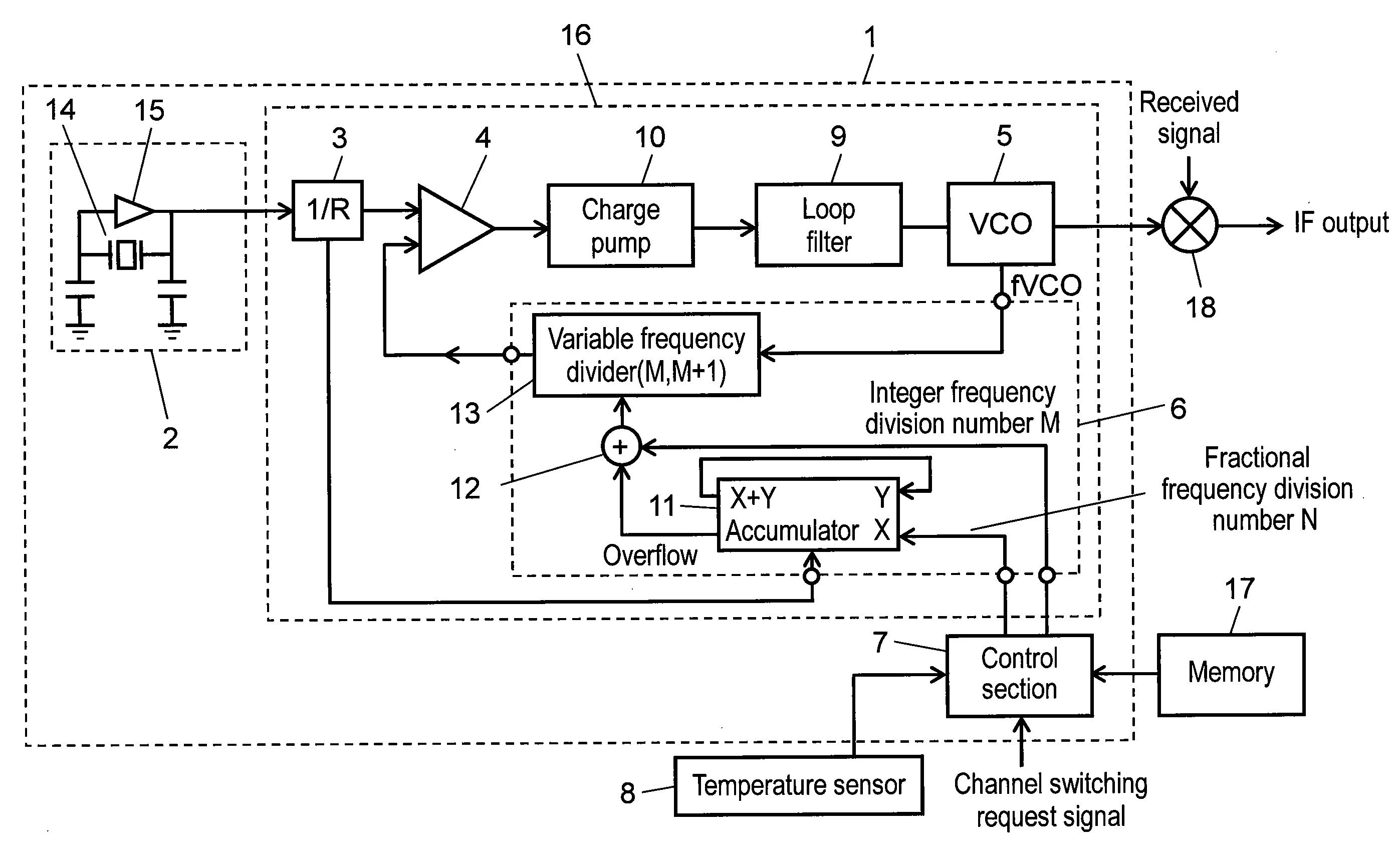
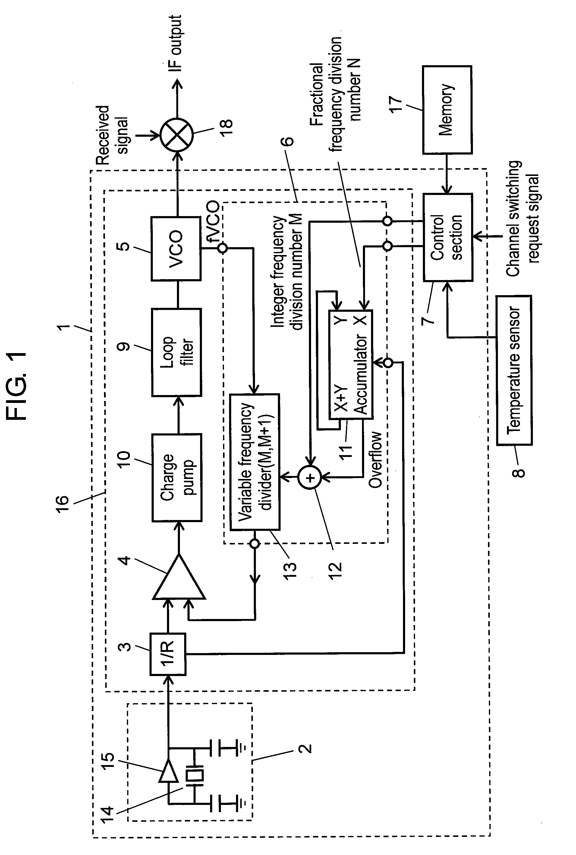
[0084]Hereinafter, a synthesizer in accordance with a first exemplary embodiment is described. FIG. 1 is a block diagram showing a synthesizer in accordance with the first exemplary embodiment of the present invention.
[0085]In FIG. 1, synthesizer 1 includes reference oscillator 2 including MEMS resonator 14 made of silicon and driver amplifier 15 for electrically driving MEMS resonator 14. Furthermore, synthesizer 1 includes synthesizer section 16 for generating an oscillation signal based on a reference oscillation signal output from reference oscillator 2 and inputting the generated oscillation signal into frequency converter 18. Synthesizer section 16 includes, for example, first frequency divider 3 for frequency-dividing the reference oscillation signal, comparator 4 for comparing an output signal from first frequency divider 3 with an output signal from second frequency divider 6, and oscillator 5 for inputting an oscillation signal into frequency converter 18 based on a signal...
second exemplary embodiment
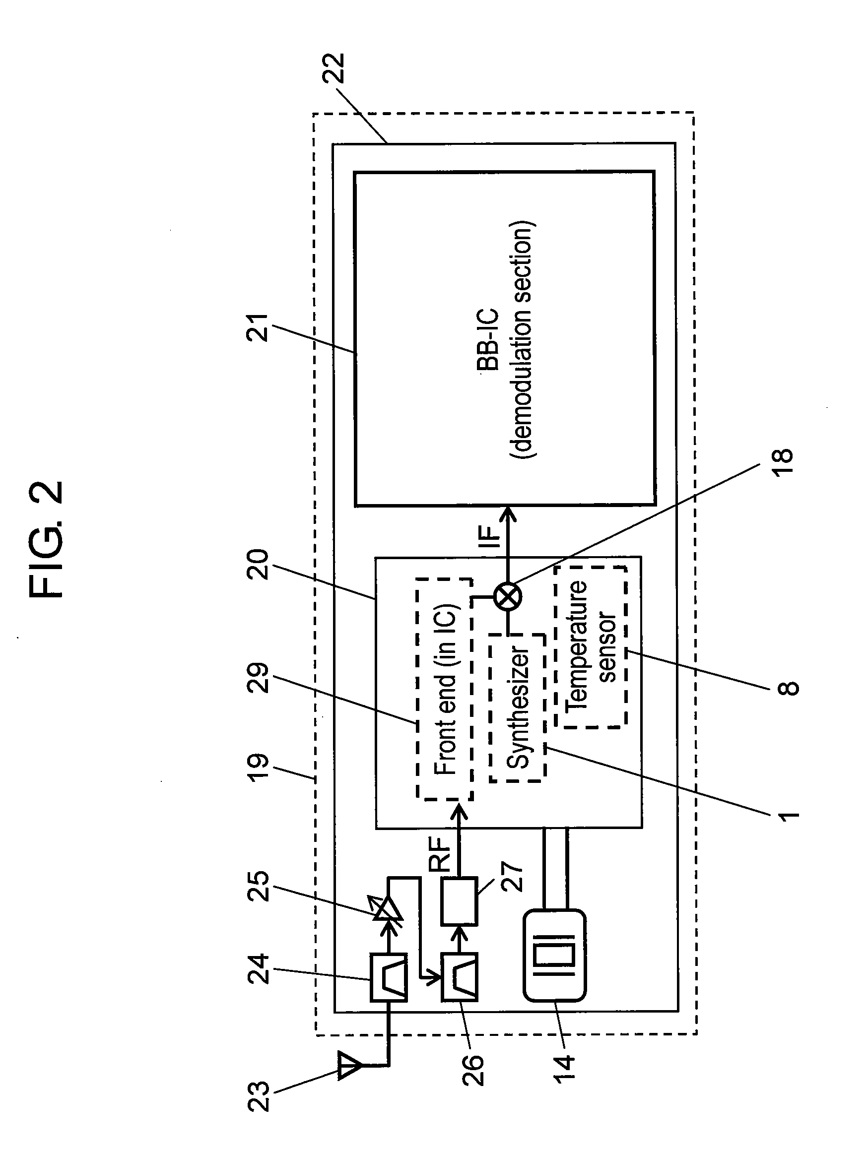
[0173]Next, an exemplary embodiment of a television reception device using a synthesizer of the present invention is described.
[0174]FIG. 12 is a block diagram showing a reception device in accordance with a second exemplary embodiment of the present invention. In FIG. 12, synthesizer 1 of the present invention together with temperature sensor 8 are integrated into the same RF-IC 20, and packaged on base substrate 19. Furthermore, MEMS resonator 14 is used as a component element of a reference oscillator, and is packaged on base substrate 19. By using MEMS resonator 14 as the component element of the reference oscillator, the size of television reception device 22 can be reduced.
[0175]For example, a quartz resonator of the equal cost has a size of 2.5×2.0 mm while the MEMS resonator can be formed in a size of 0.5×0.5 mm to 0.3 mm×0.3 mm. Furthermore, the MEMS resonator can be formed at half height or lower. In a small-size television receiving module such as a module to be installed...
third exemplary embodiment
[0190]FIG. 14 is a block diagram showing a synthesizer in accordance with a third exemplary embodiment of the present invention. In FIG. 14, synthesizer 201 of the third exemplary embodiment reduces problems when, for example, a use state of an electronic device is changed and a temperature change of synthesizer 201 becomes larger so that frequency is required to be controlled more largely. For example, at the moment when power supply of an electronic device is changed from the OFF state to the ON state, a temperature change of a reference oscillator becomes large momentarily. To a large temperature change, it is necessary to adjust a frequency by rapidly controlling a variable frequency divider. However, when frequency adjustment is carried out beyond predetermined value F, BER may be deteriorated. Furthermore, immediately after the use state of the electronic device is changed, a temperature difference may occur between a temperature sensor (or another temperature detecting mechan...
PUM
 Abstract
Description
Claims
Application Information