Road maintenance method and vehicle

a technology for road maintenance and vehicles, applied in the direction of in situ paving, roads, construction, etc., can solve the problems of insufficient uniform distribution of scrapped and cut materials, inability to easily adjust and inability to maintain the surface of roads. the effect of maintaining the stress on the cutting blade is within manageable limits and the height of cutting and smoothing blades is easy to adjus

a technology for road maintenance and vehicles, applied in the direction of in situ paving, roads, construction, etc., can solve the problems of insufficient uniform distribution of scrapped and cut materials, inability to easily adjust and inability to maintain the surface of roads. the effect of maintaining the stress on the cutting blade is within manageable limits and the height of cutting and smoothing blades is easy to adjus

US20100316444A1Inactive Publication Date: 2010-12-16WALDO LEE M

Image

  • Road maintenance method and vehicle
  • Road maintenance method and vehicle
  • Road maintenance method and vehicle

Examples


Embodiment Construction

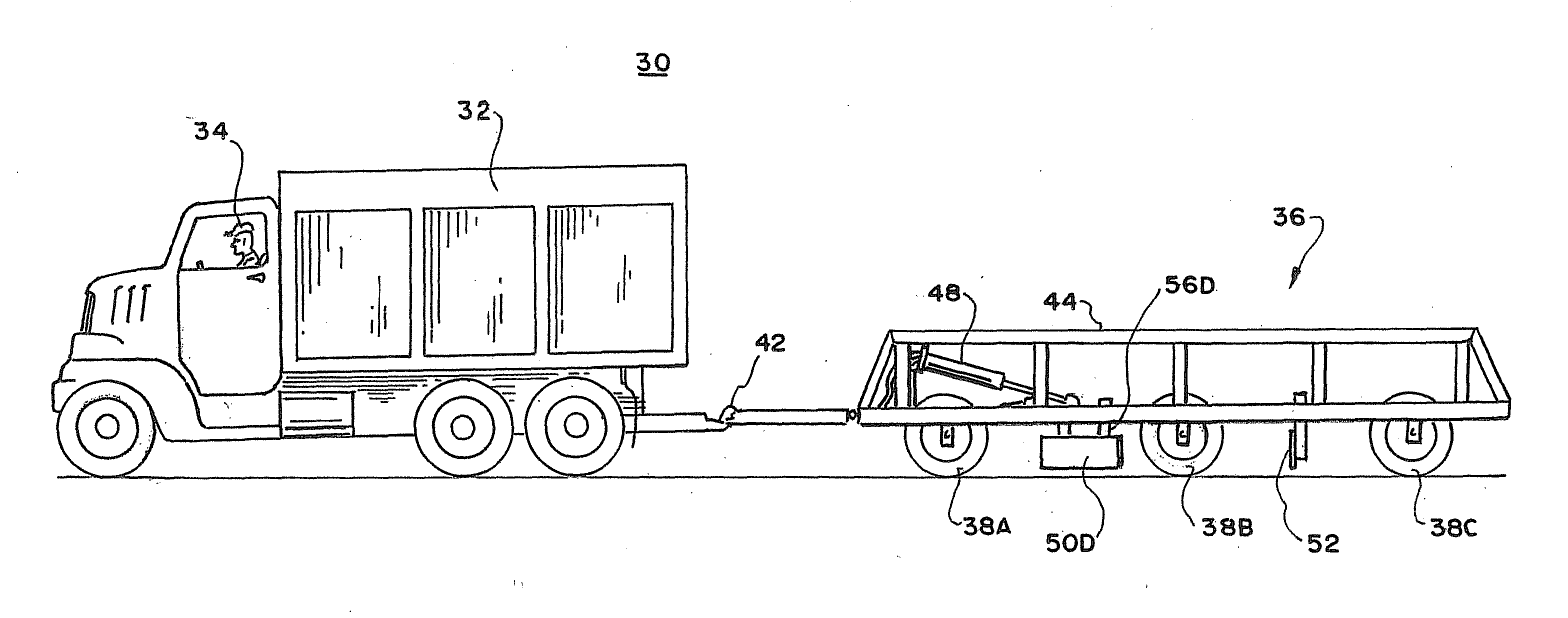
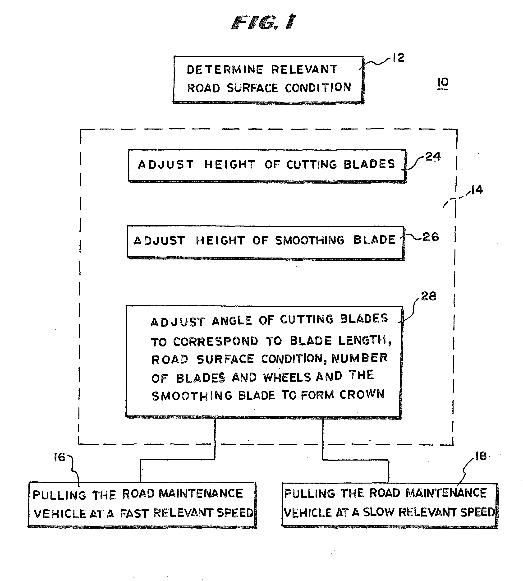
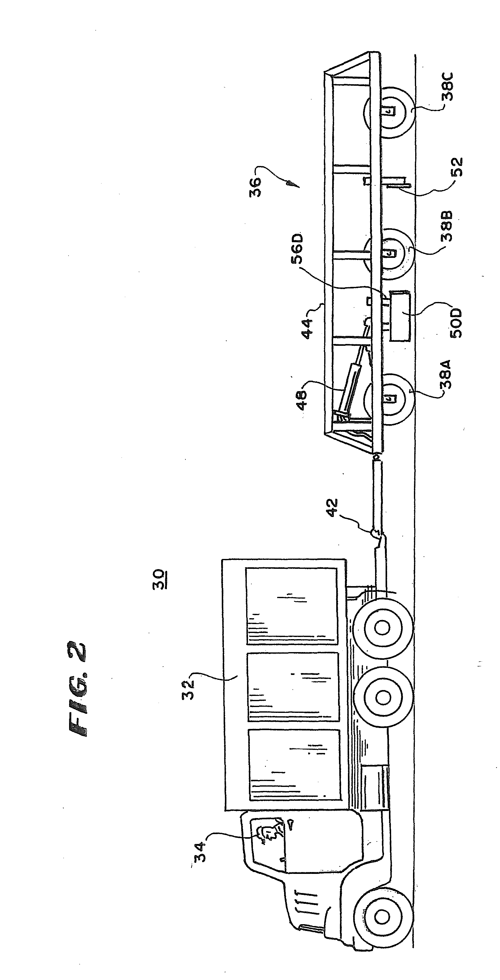
[0021]In FIG. 1 there is shown a flow diagram 10 of a process for using the road maintenance vehicle of this invention comprising the step 12 of determining relevant road surface condition, the step 14 of adjusting the cutting and smoothing blades, the step 16 of pulling the road maintenance vehicle at a fast relevant surface speed for the relevant road surface conditions and the tep 18 of pulling the road maintenance vehicle at a slow relevant speed. The step 14 of adjusting the blades for the relevant road surface conditions includes the step 24 of adjusting the height of the cutting blades within the blade-height wheel-averaging arrangement to keep the stress on the cutting blades within tolerances, the step 26 of adjusting the height of the smoothing blade to build a crown and smooth out ruts and holes, and the step 28 of adjusting the angle of the cutting blades to correspond to the length of the blades, road surface conditions, number of blades and height of the blades with re...


PUM


Abstract

The cutting blades and smoothing blades of a road maintenance vehicle are adjustable in position with respect to the wheels to avoid extremes in changes in the depth of a cut by a blade or the height of the blades caused by wheels of the vehicle dropping into low places in a road. By including a selected number of wheels mounted to the same stiff frame, the wheels riding on the highest part of the road will lift the rigid frame and other wheels rather than the wheels riding on the lowest part of the road determining the depth of the cut of the cutting blades. The height of the blades with respect to the wheels can then be adjusted so that they never cut too deep and overly stress the blades but do cut the highest elevations of the road and move the loose dirt and gravel into the lower parts of the road. A first frame is supported by wheels and a second frame is movably mounted to the first frame.

Description

RELATED CASES[0001]This application is a continuation of U.S. provisional patent application 61 / 187,596 filed Jun. 16, 2009, by inventor, Lee M. Waldo. The benefit of provisional patent application 61 / 187,596 is claimed.BACKGROUND OF THE INVENTION[0002]This invention relates to road maintenance and more particularly to methods and equipment for smoothing the surface of roads.[0003]One type of road maintenance equipment for smoothing the surface of roads includes a vehicle that is pulled by a tractor or truck and includes one or more cutting or shearing or buster blades that break elevated portions of the road into loose gravel and dirt and one or more striker or smoothing blades to spread the loose gravel and dirt over the road. One prior art road maintainer of this type has a centrally located V-shaped cutting or shearing blade and two side cutting blades that cut the road material and deliver it to a centrally located striker or smoothing blade that spreads the material across the...

Claims


Application Information

Patent Timeline
16 Dec 2010
Publication
US20100316444A1
IPC
E01C23/082; E01C23/00
CPC
E01C23/082; E02F3/7672; E02F3/7686
Inventors
WALDO, LEE M.