Radio frequency handing device
- Summary
- Abstract
- Description
- Claims
- Application Information
AI Technical Summary
Benefits of technology
Problems solved by technology
Method used
Image

Examples
first embodiment
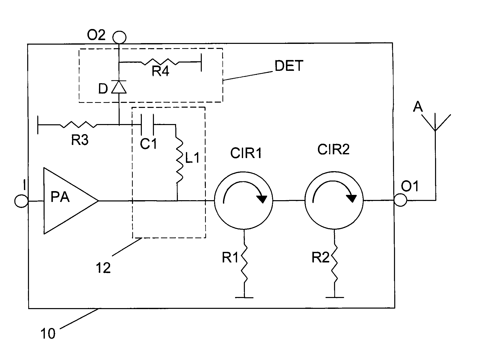
[0025]A radio frequency handling device in the form of a radio transmission device 10 is according to the present invention shown in a circuit diagram in FIG. 1. The radio transmission device 10 includes an input I on which it receives a radio frequency signal from a signal generating unit (not shown). This input is connected to the input of a power amplifier PA, the output of which is connected to a first terminal of a first circulator CIR1. The first circulator CIR1 has a second terminal connected a first terminal of a second circulator CIR2 and a third terminal connected to ground via a first matching resistor R1. The second circulator CIR2 has a second terminal connected to a first output O1 of the radio transmission device 10 and a third terminal that is also connected to ground via a second matching resistor R2. The first output O1 is connected to an antenna A. A signal scaling unit 12, indicated by a dashed box, has a first end that is also connected to the first terminal of ...
second embodiment
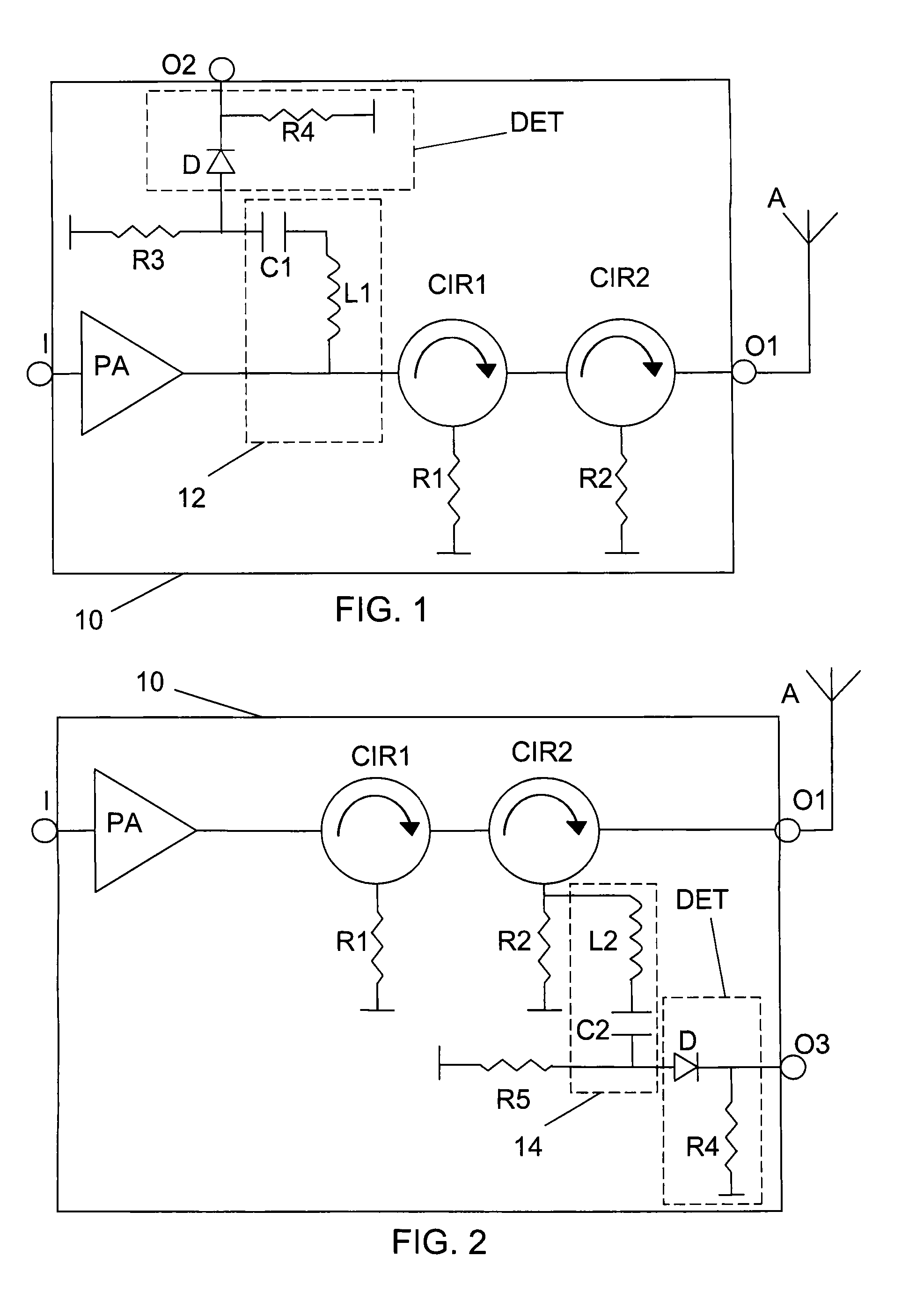
[0029]One such variation according to the present invention is described in relation to FIG. 2. FIG. 2 shows essentially the same elements as FIG. 1. However, here a signal scaling unit 14 in series with a fifth matching resistor R5 is connected in parallel with the second matching resistor R2 for the second circulator CIR2. The signal scaling unit 14 here comprises a second capacitor C2 and a second inductor L2 selected in the same way as the first capacitor C1 and first inductor L1 were selected. The detector DET is here also connected to this signal scaling unit 14 in the same way as it was connected to the signal scaling unit 12 in FIG. 1. What is measured here is not the output power; it is rather the power reflected to the second circulator CIR2, which may include signals received and reflected by the antenna A.
[0030]It should here be realised that the two embodiments may be combined, i.e. be provided in a device that both measures the transmitted power as well as reflected po...
third embodiment
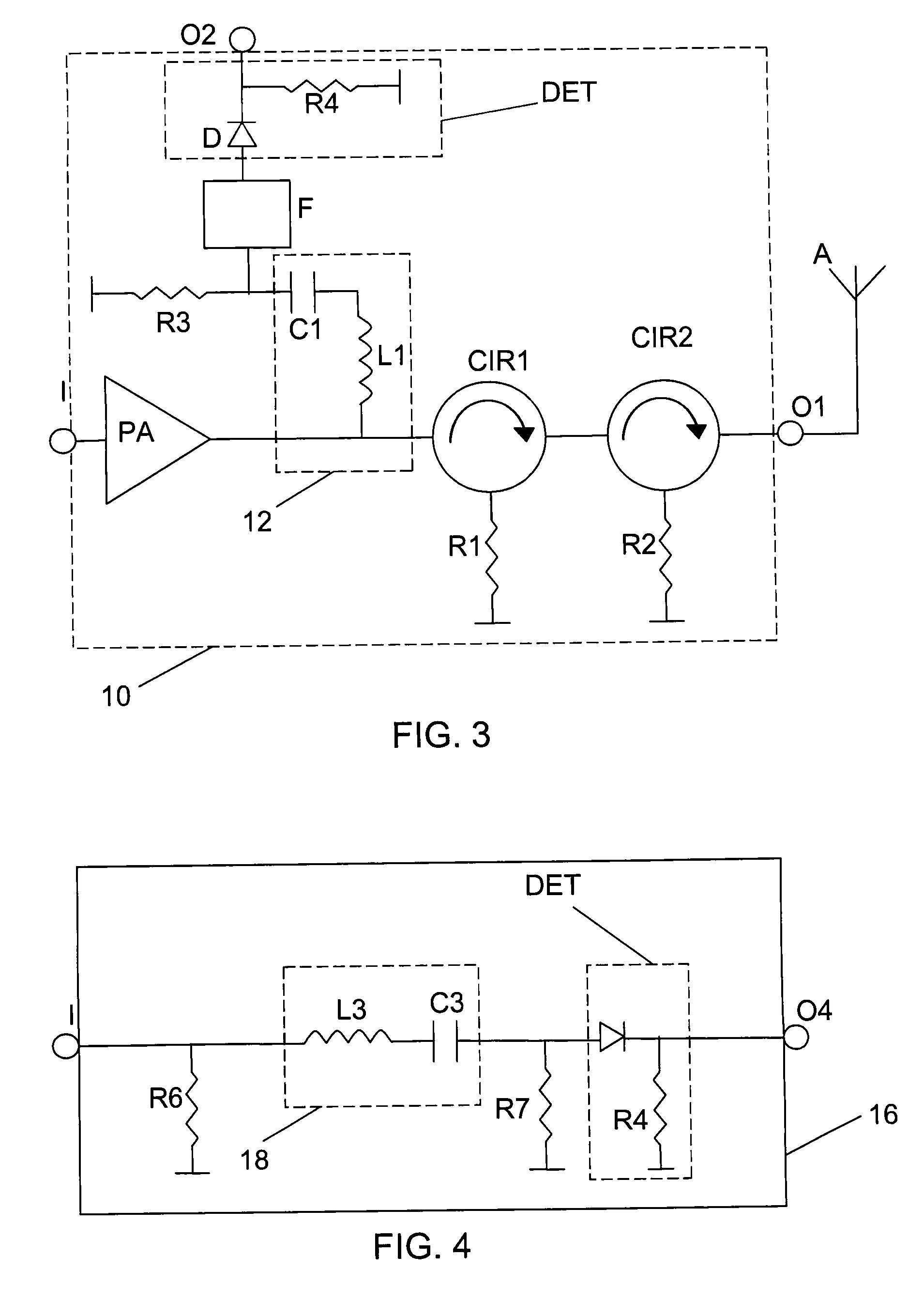
[0031]Another variation according to the present invention is shown in FIG. 3, which is essentially the same as FIG. 1. The only difference is that there is provided a filter F between the signal scaling unit 12 and the detector DET. The filter F here serves to filter out harmonics of signals that are outside of the desired frequency range in order to provide a better detection.
[0032]It is furthermore possible to use the signal scaling unit as an attenuator instead of an ordinary power attenuator. An example of this when the signal handling device is a signal attenuating device 16 according to a fourth embodiment of the present invention is shown in FIG. 4. Here there is an input I, which is connected to a signal scaling unit 18, which has the same configuration as the signal scaling units of FIG. 1-3, i.e. is provided with an inductor L3 in series with a capacitor C3. The signal scaling unit 18 is in turn connected to a detector DET of the same type as described in relation to the ...
PUM
 Abstract
Description
Claims
Application Information
 - Generate Ideas
- Intellectual Property
- Life Sciences
- Materials
- Tech Scout
- Unparalleled Data Quality
- Higher Quality Content
- 60% Fewer Hallucinations
Browse by: Latest US Patents, China's latest patents, Technical Efficacy Thesaurus, Application Domain, Technology Topic, Popular Technical Reports.
© 2025 PatSnap. All rights reserved.Legal|Privacy policy|Modern Slavery Act Transparency Statement|Sitemap|About US| Contact US: help@patsnap.com