Medical guidewire

Active Publication Date: 2010-12-16
ASAHI INTECC CO LTD
View PDF35 Cites 20 Cited by
  • Summary
  • Abstract
  • Description
  • Claims
  • Application Information

AI Technical Summary

Benefits of technology

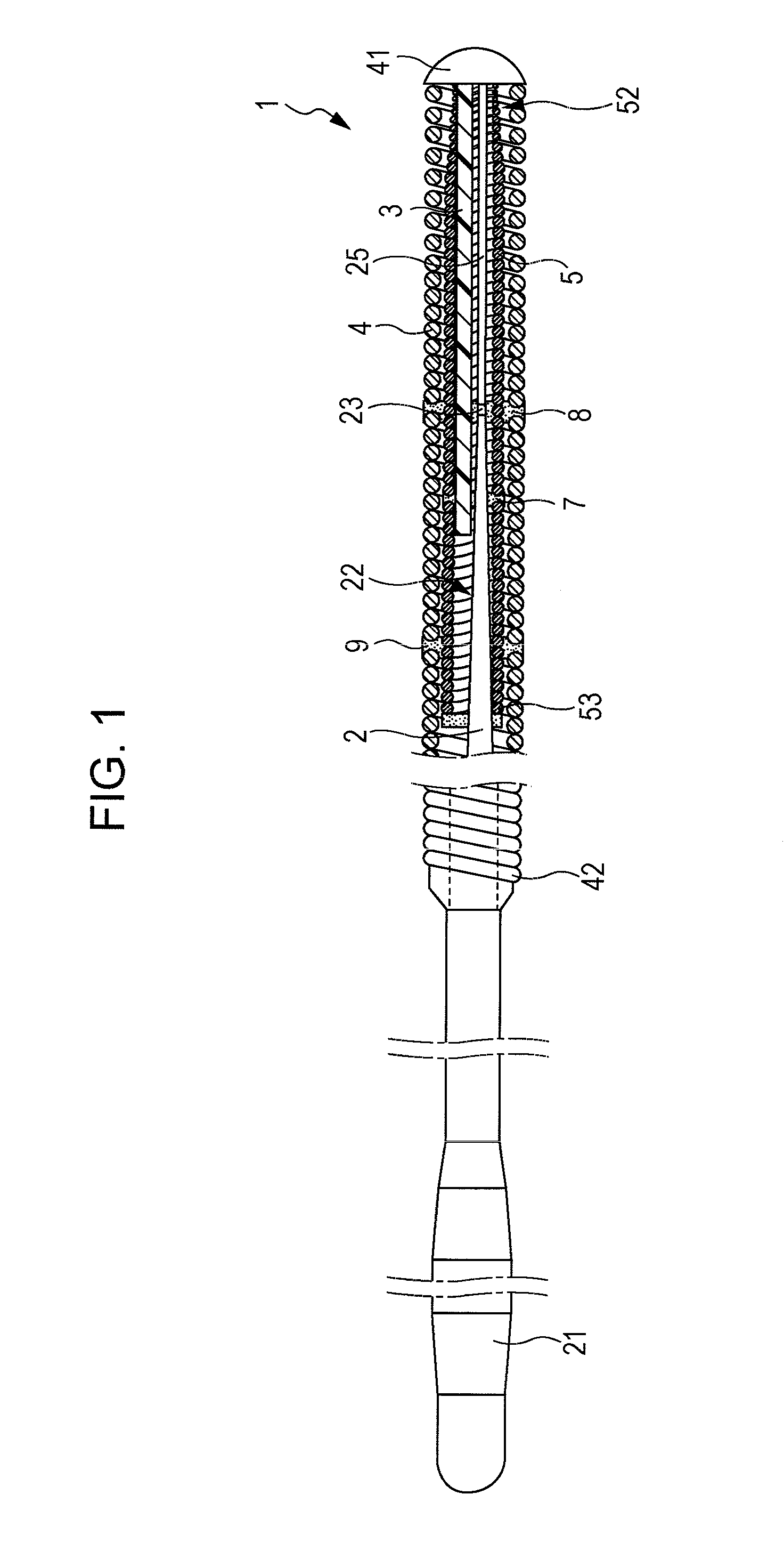
[0012]The strands of the stranded wire can move slightly relative to each other. Therefore, the stranded wire has a high degree of freedom, a high flexibility, a high resistance to plastic deformation, and a high resilience. Therefore, by disposing the stranded wire parallel to the distal end portion of the core shaft, the flexibility of the guidewire is maintained and the resilience of the guidewire after being bent into a U-shape is improved.
[0013]The hollow stranded-wire coil, which is formed of multiple strands, is disposed in the outer flexible tube and surrounds the distal end portion of the core shaft and the stranded wire. The distal ends of the hollow stranded-wire coil, the core shaft, and the stranded wire are joined to the distal end

Problems solved by technology

However, when the guidewire 100 is bent into a U-shape having a large curvature, the guidewire 100 may not recover its original shape even after the U-shaped bending is released.
Therefore,

Method used


Image

  • Medical guidewire
  • Medical guidewire
  • Medical guidewire

Examples


first embodiment

Operational Effect of First Embodiment

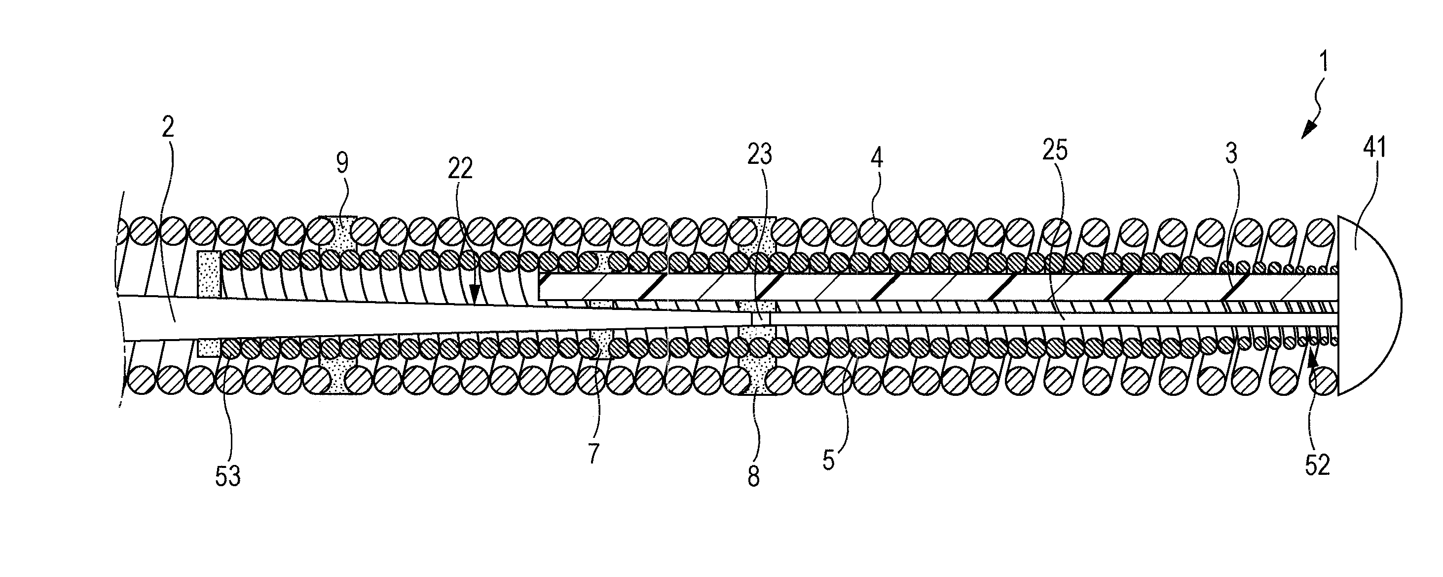
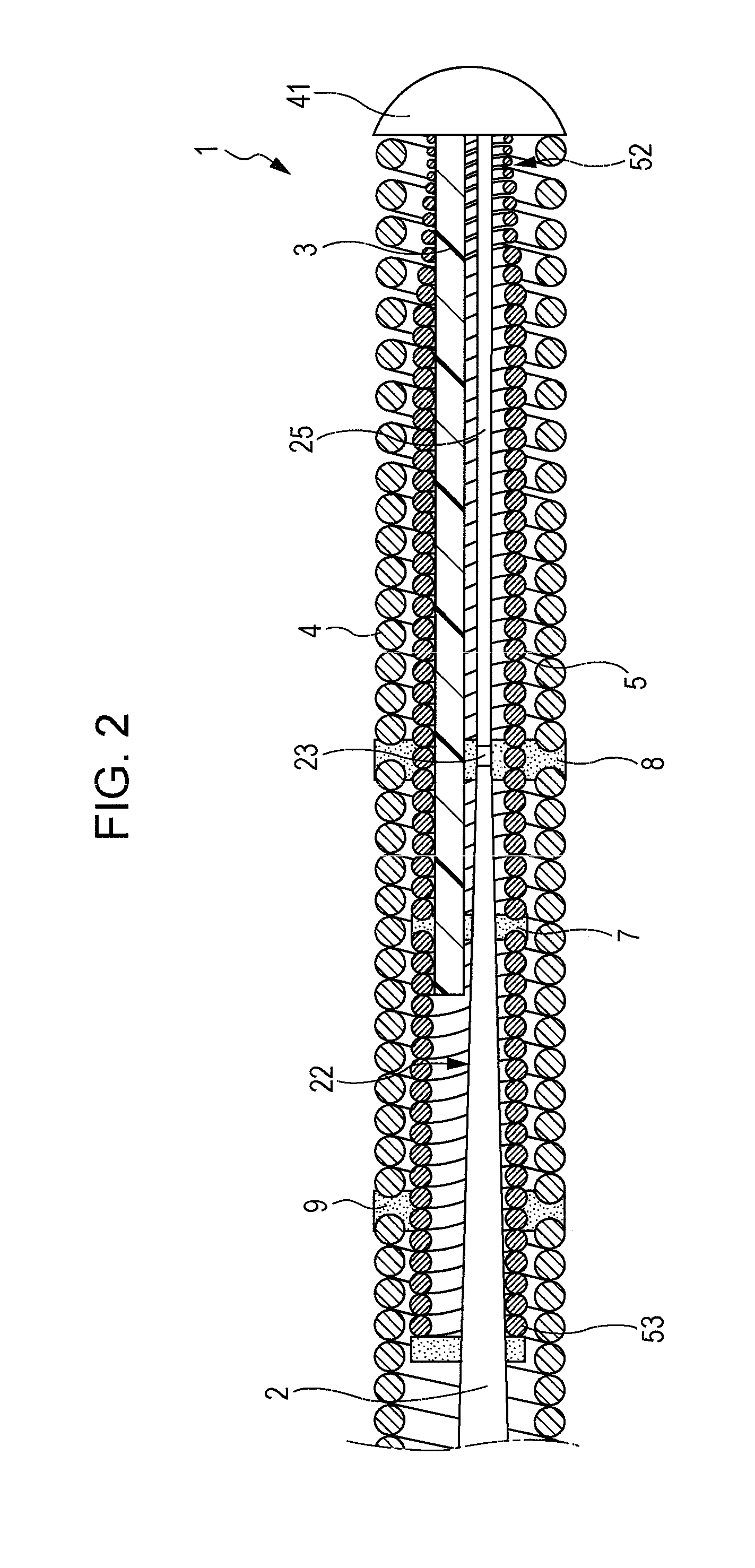
[0028]In the guidewire 1 of the first embodiment, the stranded wire 3 is disposed parallel to the distal end portion 22 of the core shaft 2. The diameter of the distal end portion 22 of the core shaft 2 decreases stepwise toward the distal end. The strands of the stranded wire 3 can move slightly relative to each other. Therefore, the stranded wire 3 has a high degree of freedom, a high flexibility, a high resistance to plastic deformation, and a high resilience. Therefore, by disposing the stranded wire 3, which has resistance to plastic deformation, parallel to the distal end portion 22 of the core shaft 2, which has a small diameter and thus has flexibility, the resilience of the guidewire 1 after being bent into a U-shape is improved while maintaining the flexibility of the guidewire 1.

[0029]The guidewire 1 includes the hollow stranded-wire coil 5, which is disposed in the outer flexible tube 4 and surrounds the distal end portion 22 of the ...


PUM


Abstract

Provided is a guidewire including a core shaft, an outer flexible tube, a stranded wire that extends parallel to the core shaft, and a hollow stranded-wire coil disposed in the outer flexible tube. The hollow stranded-wire coil is formed of multiple strands and surrounds the distal end portion of the core shaft and the stranded wire. Distal ends of the hollow stranded-wire coil, the core shaft, and the stranded wire are joined to a distal end of the outer flexible tube.

Description

BACKGROUND OF THE INVENTION[0001]1. Field of the Invention[0002]The present invention relates to a medical guidewire used for medical purposes such as inserting a catheter into a blood vessel, a ureter, or an organ or inserting an indwelling device into part of a blood vessel suffering from an aneurysm.[0003]2. Description of the Related Art[0004]In general, it is required that a medical guidewire have a flexible distal end portion. In order to fulfill such a requirement, a guidewire 100 of the related art includes a core shaft 101 and a coil spring 102 that surrounds the core shaft 101, and the diameter of a distal end portion 103 of the core shaft 101 is made small so as to improve flexibility (see FIG. 4).[0005]When using the guidewire 100 to guide a device, such as a catheter or an indwelling device, to a target region in a human body, the distal end portion of the guidewire 100 may be unintentionally bent into a U-shape. For some operations, the guidewire 100 is bent into a U-s...

Claims


Application Information

Patent Timeline
IPC IPC(8): A61M25/09
CPCA61M25/09A61M2025/09091A61M2025/09175A61M2025/09083
Inventor MIYATA, NAOHIKONAGANO, SATOSHINISHIGISHI, MAKOTO
Owner ASAHI INTECC CO LTD
Why Eureka
Try Eureka