
Human-machine-interface and method for manipulating data in a machine vision system

a machine vision system and human-machine interface technology, applied in the field of machine vision systems, can solve the problems of insufficient evidence of object location in the field of view, and cannot be strictly consecutive, and achieve the effects of less expensive, much higher speed, and easy setting up

Active Publication Date: 2010-12-16
COGNEX CORP
View PDF41 Cites 26 Cited by
  • Summary
  • Abstract
  • Description
  • Claims
  • Application Information

AI Technical Summary

Benefits of technology

This invention provides a graphical user interface (GUI) that works with a machine vision system to create a more intuitive and industrial-like appearance and layout. The GUI includes a centralized image frame window surrounded by panes with buttons and specific interface components that the user employs in each step of the machine vision system set up and run a new machine vision job. The GUI also includes a filmstrip with specialized highlighting that indicates useful information about the underlying images. The filmstrip controls include a selector that allows the user to switch between image modes. The vision system is set up and run using a sequential series of buttons or switches that are activated by the user in a predefined order to perform each of the steps needed. The programming of logic is performed using a programming window that includes a ladder logic arrangement. The user can define additional rungs and the contacts for each rung can be based upon output coils of previous rungs or upon recognition / detection results. The thumbnail window is provided on the programming window in which an image from a filmstrip is displayed, focusing upon the locations of the image (and underlying viewed object / part) in which the selected contact element is provided.

Problems solved by technology

These frames may not be strictly consecutive, however, because as the object passes through the field of view there may be some viewing perspectives, or other conditions, for which the evidence that the object is located in the field of view is not sufficient.

Method used


Image

  • Human-machine-interface and method for manipulating data in a machine vision system
  • Human-machine-interface and method for manipulating data in a machine vision system
  • Human-machine-interface and method for manipulating data in a machine vision system

Examples


Embodiment Construction

A. Implementation of an Exemplary Machine Vision Detector

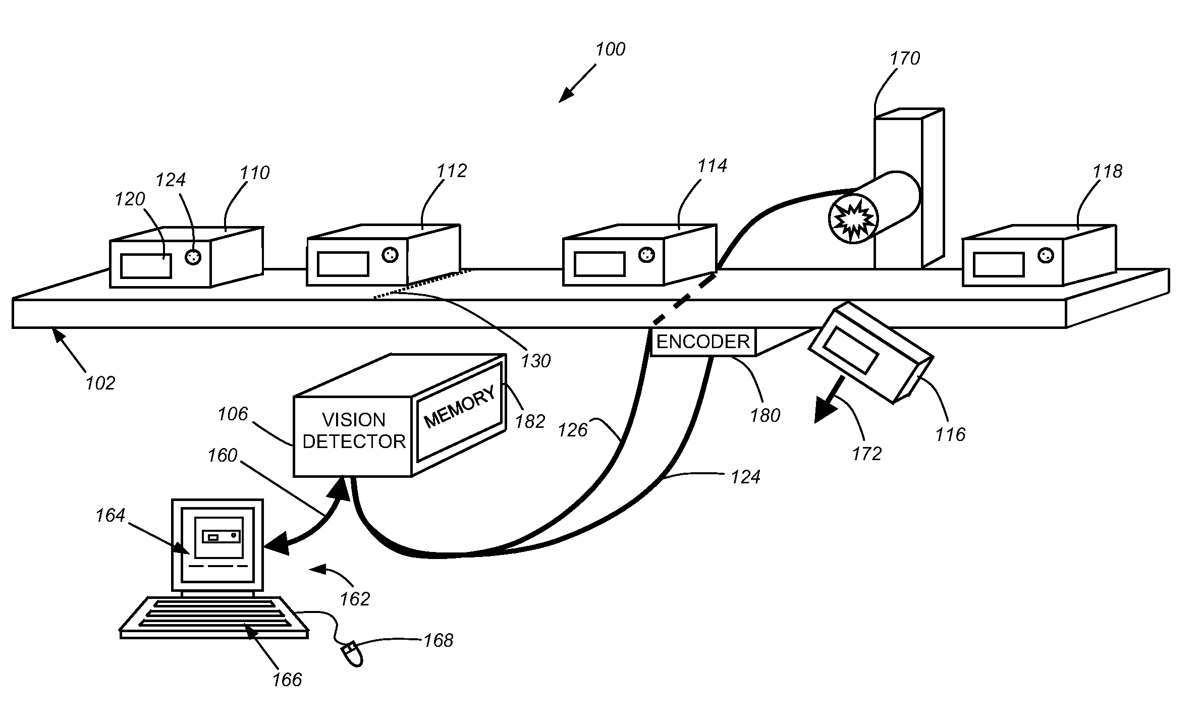
[0043]FIG. 1 shows an example of an exemplary machine vision system to which the teachings of this invention may be applied. The system is a vision detector system 100 as described above, and as set forth generally in the above-incorporated, U.S. Published Patent Application No. US200550275831A1, entitled METHOD AND APPARATUS FOR VISUAL DETECTION AND INSPECTION OF OBJECTS, by William M. Silver. It should be noted that, while this Description references a vision detector as the exemplary operative machine vision implementation, the teachings of an HMI described and claimed herein are expressly applicable to a wide range of vision systems. Thus, the HMI functions and layout described herein should be taken as broadly applicable to any system requiring setup, monitoring, feedback of inspection data and the like. Such systems include, but are not limited to, the exemplary vision detector, a more complete machine vision inspection ...


PUM


Abstract

This invention provides a Graphical User Interface (GUI) that operates in connection with a machine vision detector or other machine vision system, which provides a highly intuitive and industrial machine-like appearance and layout. The GUI includes a centralized image frame window surrounded by panes having buttons and specific interface components that the user employs in each step of a machine vision system set up and run procedure. One pane allows the user to view and manipulate a recorded filmstrip of image thumbnails taken in a sequence, and provides the filmstrip with specialized highlighting (colors or patterns) that indicate useful information about the underlying images. The programming of logic is performed using a programming window that includes a ladder logic arrangement.

Description

RELATED APPLICATIONS[0001]This application is a divisional of commonly assigned copending U.S. patent application Ser. No. 11 / 616,726, filed Dec. 27, 2006, entitled HUMAN-MACHINE-INTERFACE AND METHOD FOR MANIPULATING IN A MACHINE VISION SYSTEM, which is a continuation-in-part of commonly assigned copending U.S. patent application Ser. No. 11 / 138,025 which was filed, May 26, 2005, by William M. Silver, et al., for a METHOD AND APPARATUS FOR AUTOMATIC VISUAL DETECTION, RECORDING, AND RETRIEVAL OF EVENTS, which is a continuation-in-part of commonly assigned, copending U.S. patent application Ser. No. 11 / 059,512, which was filed Feb. 16, 2005, by William M. Silver, et al., for a METHOD AND APPARATUS FOR AUTOMATIC VISUAL DETECTION, RECORDING, AND RETRIEVAL OF EVENTS, which is a continuation-in-part of commonly assigned, copending U.S. patent application Ser. No. 10 / 865,155, which was filed on Jun. 9, 2004, by William M. Silver for a METHOD AND APPARATUS FOR VISUAL DETECTION AND INSPECTIO...

Claims


Application Information

Patent Timeline
Patent Type & Authority Applications(United States)
IPC IPC(8): G06F3/048G06K9/00G06T7/20
CPCG06K9/6253G06T7/0004G06T2200/24G06F9/4443Y10S715/972G06F3/0481H04N5/225G06F9/451G06V10/945G06F18/40H04N23/00
Inventor TREMBLAY, ROBERT J.PHILLIPS, BRIAN S.KEATING, JOHN F.EAMES, ANDREWWHITMAN, STEVENMIRTICH, BRIAN V.ARBOGAST, JR., CARROLL MCNEILL
Owner COGNEX CORP
Learn More