Tension cord fastener structure

Inactive Publication Date: 2010-12-23
LIN CHIEH JEN
View PDF17 Cites 4 Cited by
  • Summary
  • Abstract
  • Description
  • Claims
  • Application Information

AI Technical Summary

Benefits of technology

[0005]With the pivot of the pivot-carrying fastening member received in the bore of the bore-carrying fastening member, the pivot-carrying fastening member and the bore-carrying fastening member are rotatable with respect to each other about the pivot for selectively opening and closing. When the pivot-carrying fastening member and the bore-carrying fastening member are opened, an elastic object can be positioned between the pivot-carrying fastening member and the bore-carrying fastening member and then the fastening members are closed to allow a pawl formed on a lower portion of the locking member to slide over a locking sliding face of the bore-carrying fastening member so that the flanges of the locking member can be slidably fit into the receiving channels of the pivot-carrying fastening member and the bore-carrying fastening member to secure the fastening members together thereby fastening elastic object that is received in the bore in position inside the fastener structure. Being different from the existing techniques that employs a knot or a stop member to fix the elastic object, the present invention uses the concave arc surfaces of the fastening members and the locking member that constitute a conic bore of which an upper end diameter is greater than a lower end diameter thereof to fasten an elastic object, so that the elastic object, when stretched and thus deformed, is subjected to constraint imposed by the conic bore, causing expansion of diameter at the end thereof to thereby make tight engagement with the concave arc surfaces so as to effectively secure and fasten the end of the elastic object. Further, with the arrangement of the locking member, besides the effectively realized operation safety and secured fastening, easy replacement and adjustment of the elastic object are also realized.

Problems solved by technology

However, such a material of light weight and high extensibility is hard to have ends thereof properly and securely fastened.
An unexpected loosening of the elastic object during the use thereof may cause danger.
Further, fastening an elastic object in such a way often makes it difficult, if not impossible, to release the elastic object for replacement and thus cause certain troubles in the use of the elastic object.

Method used


Image

  • Tension cord fastener structure
  • Tension cord fastener structure
  • Tension cord fastener structure

Examples


Embodiment Construction

[0014]The following descriptions are exemplary embodiments only, and are not intended to limit the scope, applicability or configuration of the invention in any way. Rather, the following description provides a convenient illustration for implementing exemplary embodiments of the invention. Various changes to the described embodiments may be made in the function and arrangement of the elements described without departing from the scope of the invention as set forth in the appended claims.

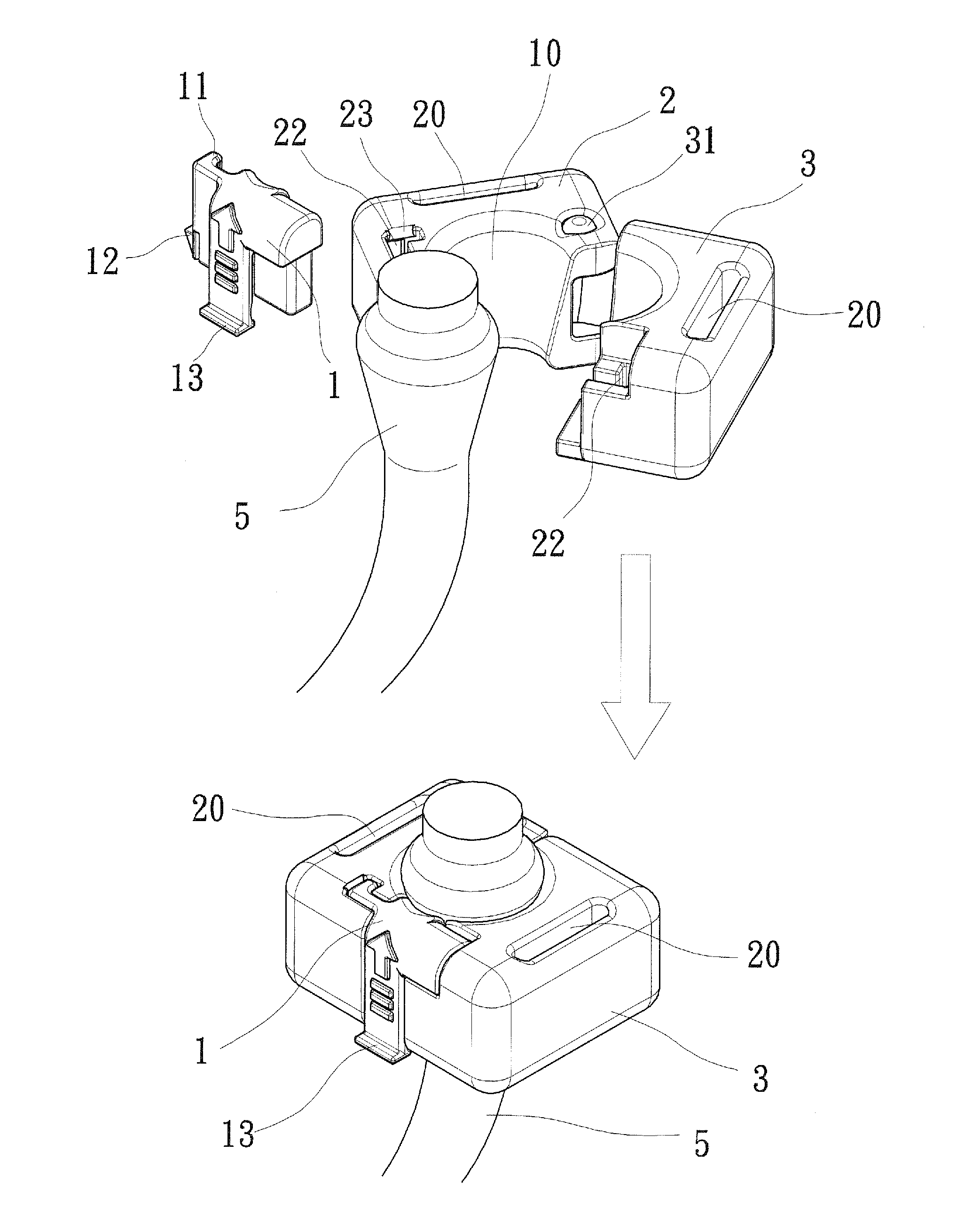
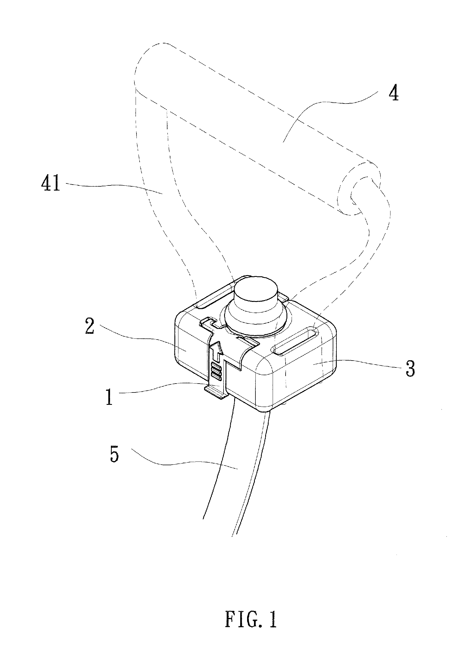
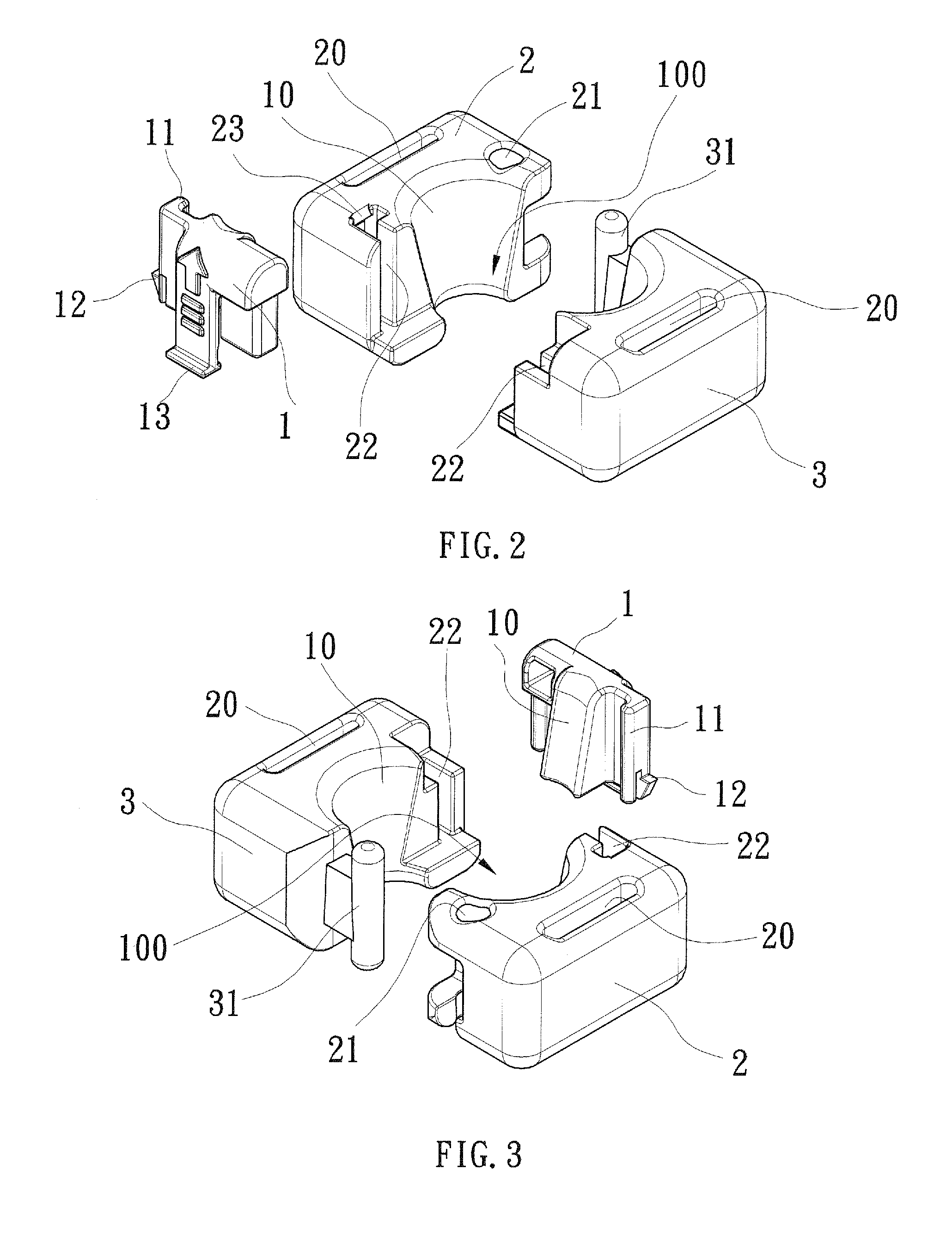
[0015]A preferred embodiment of a fastener structure according to the present invention will be illustrated hereinafter, with reference to the attached drawings, in order to give a description to the structure and function thereof for the purposes of better understanding of the present invention. As shown in FIGS. 1-6, the present invention provides a fastener structure for a tension cord and the tension cord fastener of the present invention comprises a locking member 1, a bore-carrying fastening m...


PUM


Abstract

A fastener structure is provided for fastening an elastic object and includes a bore-carrying fastening member and a pivot-carrying fastening member, which form grip band receiving holes and receiving channels and which have inner sides forming concave arc surfaces. The bore-carrying fastening member forms a bore that rotatably receives a pivot formed on the pivot-carrying fastening member therein. The locking member forms two flanges, which are respectively receivable in the receiving channels of the bore-carrying fastening member and the pivot-carrying fastening member so that the bore-carrying fastening member and the pivot-carrying fastening member are combinable together with the locking member with the concave arc surfaces of the bore-carrying fastening member and the pivot-carrying fastening member and a concave arc surface of the locking member together define and delimit a conic bore for receiving and fastening the elastic object.

Description

TECHNICAL FIELD OF THE INVENTION[0001]The present invention generally relates to a tension cod fastener structure, which comprises a bore-carrying fastening member, a pivot-carrying fastening member, and a locking member, which are releasably combinable to fasten an end of a tension cord therebetween and prevent the tension cord from sliding off the fastener structure in the use thereof.DESCRIPTION OF THE PRIOR ART[0002]Body fitting facility or exercise equipments often use an elongate elastic object, which is for example a metal spring or a cord made of synthetic fibers or high-molecule polymers each having its own advantages and disadvantages. Among these elastic objects, a high-molecule polymer cord has the advantages of light weight and high extensibility and is easy for carrying and use. However, such a material of light weight and high extensibility is hard to have ends thereof properly and securely fastened. An unexpected loosening of the elastic object during the use thereof...

Claims


Application Information

Patent Timeline
IPC IPC(8): A44B99/00
CPCA63B21/1434Y10T24/44017A63B21/1469A63B21/1438A63B21/4035A63B21/4019A63B21/4017A61P35/00
Inventor LIN, CHIEH-JEN
Owner LIN CHIEH JEN
Why Eureka
Try Eureka