Hinge for automatically-closing door which opens in both directions and structure for door which opening in both directions

a technology of automatic closing and hinges, which is applied in the direction of hinges, manufacturing tools, wing accessories, etc., can solve the problems of not being able to install on a door which opens in both directions, and achieve the effects of low cost, simple structure and easy manufacturing

Inactive Publication Date: 2010-12-23
SAWA CORP
View PDF18 Cites 27 Cited by
  • Summary
  • Abstract
  • Description
  • Claims
  • Application Information

AI Technical Summary

Benefits of technology

[0014]According to the present invention, when the door is opened inward, the each sphere moves relatively with respect to one of the inclined portions of the substantially V-shaped groove. When the door is opened outward, the each sphere moves relatively with respect to the other inclined portion of the substantially V-shaped groove. Therefore, the door which opens in both directions and which can be opened and closed both inward and outward can be automatically closed with the compression coil spring, and the shock of a door closing action of the door which opens in both directions can be absorbed by the hydraulic pressure or the pneumatics. Since the structure is simple, it can be manufactured easily at a low cost, and downsizing and hence saving of the installation space can also be achieved. Also, with the configuration in which the spheres are engaged with the substantially V-shaped grooves, the inclination or the pitch of the substantially V-shaped grooves can be set freely and adapted freely to the opening and closing states of the door which opens in both directions such as the degree of opening of the door which opens in both directions. With the configuration in which the spheres move along the substantially V-shaped grooves, the spheres move smoothly with a low frictional resistance, and the piston is smoothly traveled, so that the smoothening of the opening and closing actions of the door which opens in both directions is achieved.
[0015]Also, by forming the substantially V-shaped grooves so as to continue circumferentially, the manufacturing process is simplified.
[0016]Also, the shock absorbing mechanism operated in conjunction with the forward and backward movement of the piston is obtained easily at a low cost by fixing the another piston to the piston, forming the first and second fluid chambers by the piston, the another piston and the diaphragm, and configuring the fluid pressure shock absorbing mechanism by allowing the fluid to circulate between the first and second fluid chambers. With the configuration as described above, the shock absorbance superior in stability is also achieved.

Problems solved by technology

Incidentally, the above-described automatically-closing door hinge configured to use hydraulic pressure or pneumatics to absorb a shock applied when closing the door is designed for one-side opening doors, which is opened outward or inward, and hence cannot be installed on a door which opens in both directions, that is opened both inward and outward.

Method used


Image

  • Hinge for automatically-closing door which opens in both directions and structure for door which opening in both directions
  • Hinge for automatically-closing door which opens in both directions and structure for door which opening in both directions
  • Hinge for automatically-closing door which opens in both directions and structure for door which opening in both directions

Examples


Embodiment Construction

[0021]Referring now to the drawings, embodiments of the invention will be described.

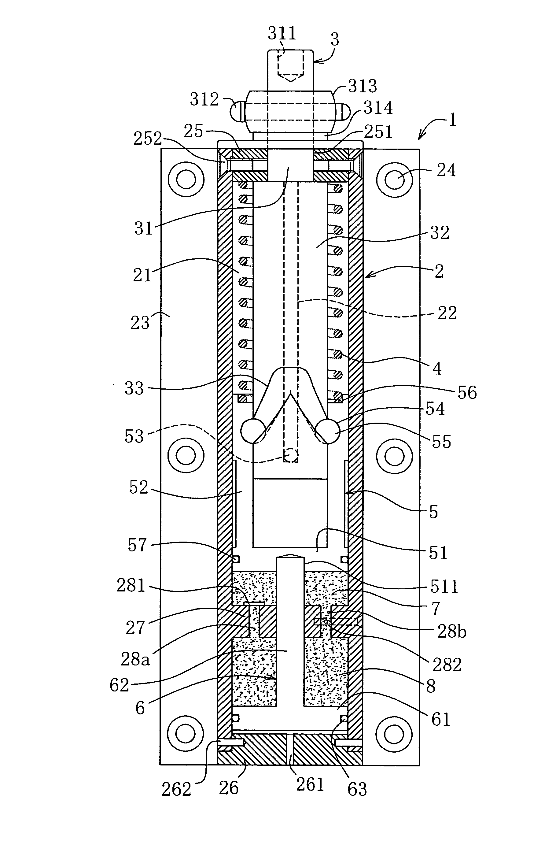
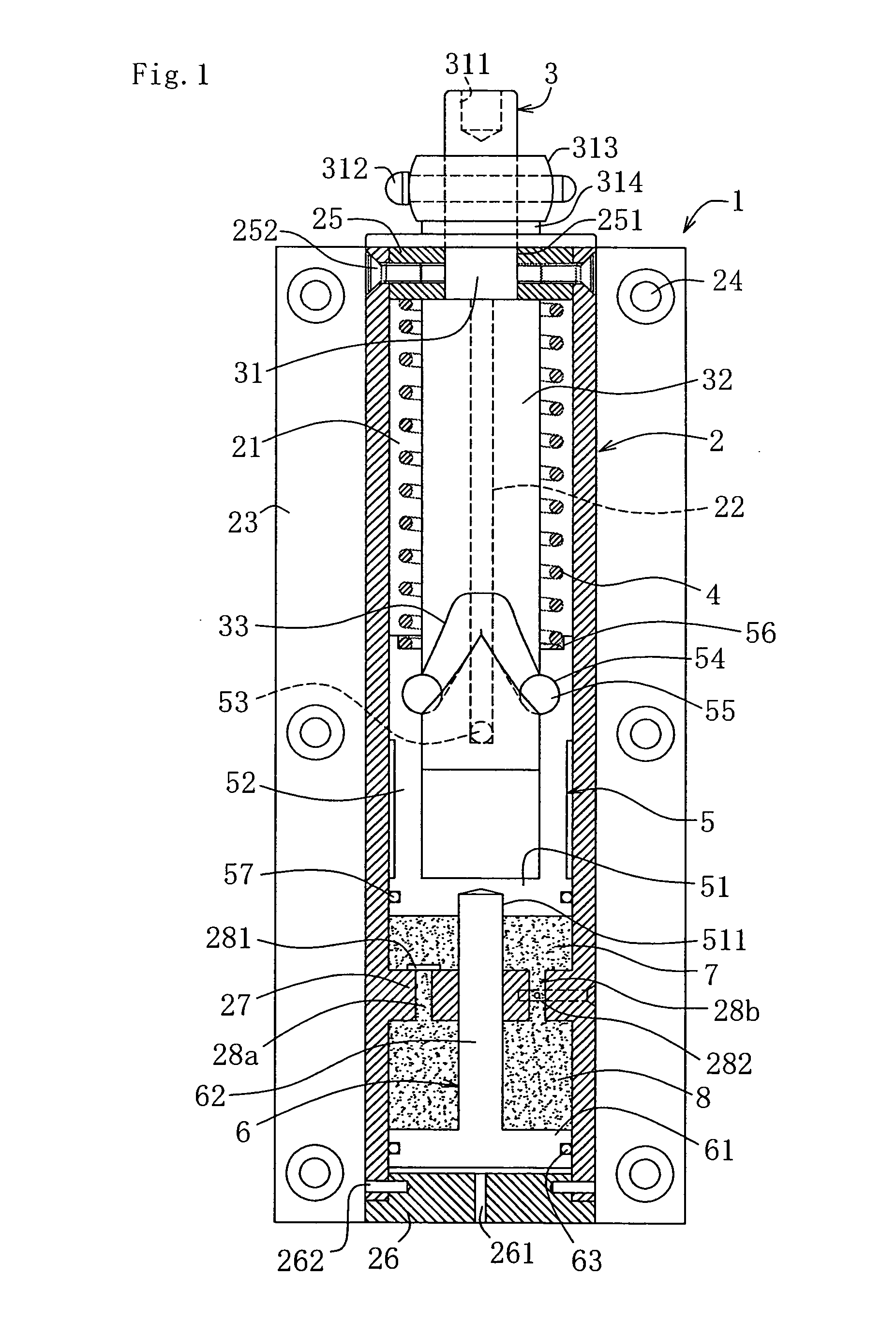
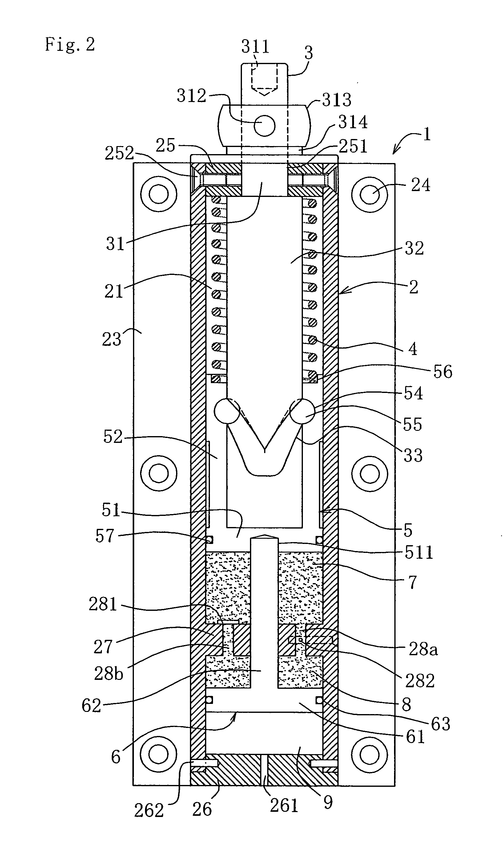
[0022]A hinge for automatically-closing a door which opens in both directions 1 according to this embodiment includes a cylinder 2, an operating rod 3 rotatably attached to the cylinder 2 so as to project partly outward from an upper end side of the cylinder 2, a compression coil spring 4 mounted in the cylinder 2 and arranged on an outer periphery of the operating rod 3, an upper piston 5 mounted in the cylinder 2 and arranged on the outer periphery of the operating rod 3, and a lower piston 6 mounted in the cylinder 2 and attached to a lower side of the upper piston 5 as shown in FIG. 1 and FIG. 2.

[0023]The cylinder 2 has a hollow portion 21 of a substantially cylindrical shape, and is formed with depressed grooves 22 at front and rear positions of an inner surface thereof respectively so as to extend in the vertical direction. A rectangular mounting panel 23 is integrally formed on a back surface ...


PUM


Abstract

A hinge for automatically-closing a door which opens in both directions with a shock absorbing function, which allows installation on a door which opens in both directions and is opened inward and outward, including a cylinder 2; an operating rod 3 attached to one end of the cylinder 2 so as to be rotatable and restricted from moving in the longitudinal direction; two substantially V-shaped grooves 33 provided on an outer periphery of the operating rod 3 in the cylinder 2 so as to oppose to each other; two spheres 55 provided so as to engage the substantially V-shaped grooves 33 and disposed so as to oppose to each other; an upper piston 5 engaged with the spheres 55 and moved in the cylinder 2 in the longitudinal direction in conjunction with the movement of the spheres 55 with respect to the substantially V-shaped groove 33; a compression coil spring 4 disposed between the upper piston 5 and an upper end portion of the cylinder 2 and configured to urge the upper piston 5 to the other end side of the cylinder 2; and a fluid pressure shock absorbing mechanism configured to absorb a shock caused by the movement of the upper piston 5 to the other end side with a liquid pressure.

Description

TECHNICAL FIELD[0001]The present invention relates to a hinge for automatically-closing a door which opens in both directions, having a buffering function, and structure for a door which opens in both directions having the hinge for automatically-closing a door which opens in both directions.BACKGROUND ART[0002]In the related art, an automatically-closing door hinge configured to rotate an opened door in a closing direction automatically using a restoring force of a coil spring and provided with a shock absorbing function for absorbing a shock applied when the door is closed using a hydraulic cylinder is known and, in recent years, an automatically-closing door hinge configured to absorb a shock with an air damper instead of the hydraulic cylinder is proposed. For example, disclosed in Patent Document 1 (JP-A-2002-303072) and Patent Document 2 (JP-A-2005-113682) are an automatically-closing door hinge on the basis of an air damper including a piston stored and arranged in a cylinder...

Claims


Application Information

Patent Timeline
Patent Type & Authority Applications(United States)
IPC IPC(8): E05F15/04E05F3/20E05D3/08E05F3/04E05F3/02
CPCE05F1/1223Y10T16/5393E05Y2201/638E05Y2900/132E05D15/54E05Y2201/474E05Y2201/696E05Y2201/256E05Y2201/264E05Y2201/478E05Y2800/205E05Y2800/21Y10T16/283Y10T16/2771Y10T16/304Y10T16/53984E05F3/20E05D3/08E05D7/086E05F1/12E05F3/02
Inventor SAWA
Owner SAWA CORP
Why Eureka
Try Eureka