Shear Seal Blowout Preventer

Active Publication Date: 2010-12-23
NAT OILWELL VARCO LP
View PDF43 Cites 51 Cited by
  • Summary
  • Abstract
  • Description
  • Claims
  • Application Information

AI Technical Summary

Benefits of technology

[0009]The shear/seal ram disclosed herein solves these drawbacks by providing a knife edge in a shearing orifice and the knife edge is inclined to minimize the cutting force required and to leave a clean cut edge. The knife edge is presented in the orifice or opening of the ram, thus the opening is positioned at the axis of the BOP, and consequently the coiled tubing, be

Problems solved by technology

Some of such devices include shear arrangements which are generally rectangular in configuration but the configuration or arrangement is such that it may collapse or crush the ends of the tubular member being severed, particularly where the member is thin walled.
Also, the sealing arrangement employed with such shear blades is generally unsatisfactory in that it may not adequately and positively seal or block off communication through the BOP after the tubular members or other object has been severed.
While the structure disclosed in the '825 patent has proved successful, it still suffers from the drawback that the ram element requires a polymeric seal component.
It is known that polymeric components of all types become brittle with age, particularly in the harsh environment of a blowout preventer.
If the seal element becomes brittle, then the seal can leak by, reducing the effectiveness for which the BOP was installed.
The gate valve shear seal arrangement, howeve

Method used


Image

  • Shear Seal Blowout Preventer
  • Shear Seal Blowout Preventer
  • Shear Seal Blowout Preventer

Examples


Embodiment Construction

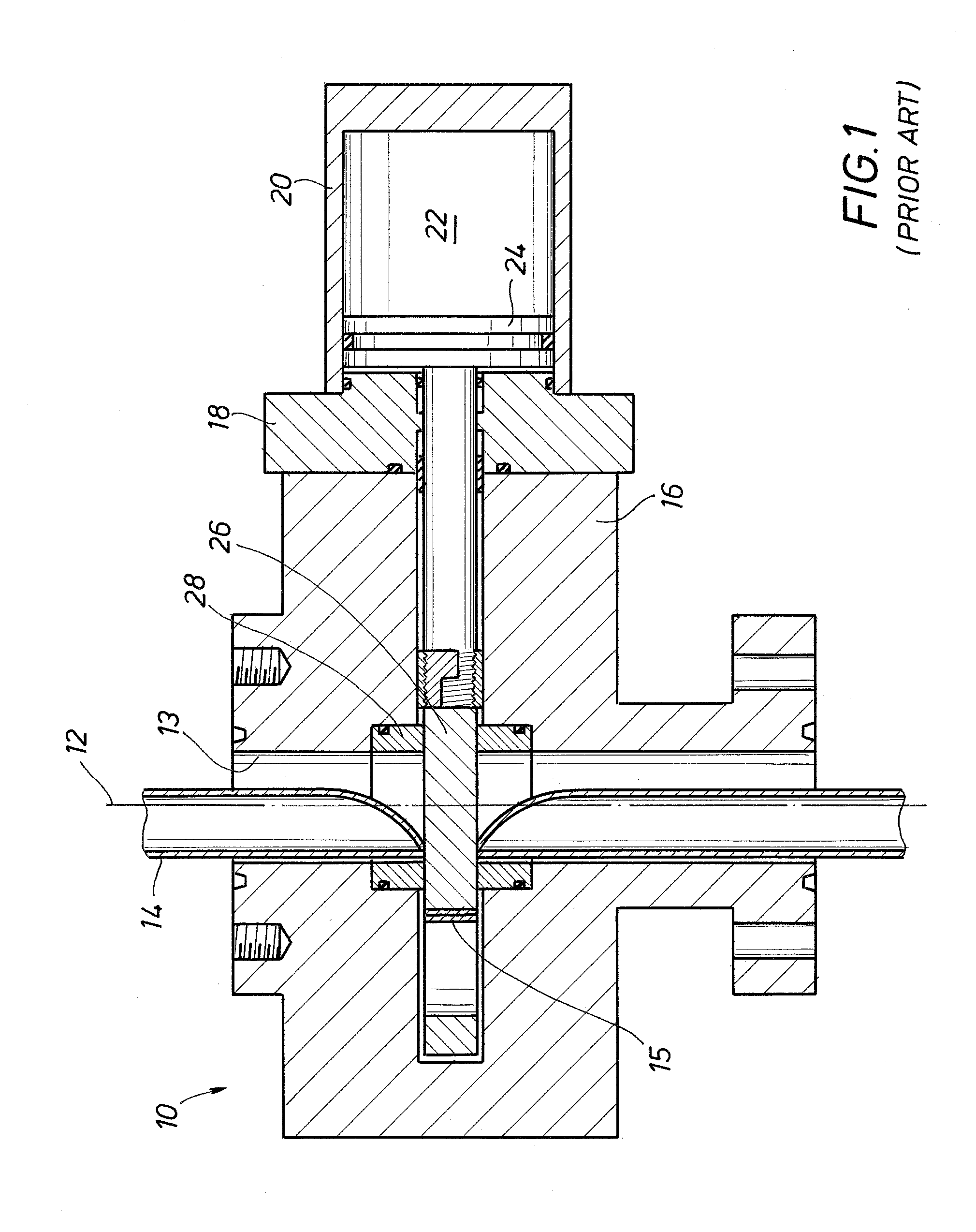
[0026]FIG. 1 depicts a known shear / seal ram-type BOP 10 oriented along an axis 12 of a bore 13. The BOP 10 is shown in an actuated condition, having sheared a coiled tubing 14. Thus, a section 15 (referred to as a “biscuit”) of the coiled tubing 14 has been removed from the coiled tubing, and may ultimately fall down the bore or otherwise interfere with further operation or recovery of the BOP.

[0027]The BOP 10 includes a body 16 through which the bore 13 is formed. A seal cap 18 is secured to the body 16, such as by bolting, and the seal cap 18 supports a cylinder body 20. A chamber 22 within the cylinder body 20 actuates a piston 24 which is operatively coupled to a shear ram 26. The shear ram 26 is moved back and forth horizontally, perpendicular to the bore 13, and is sealed on the top and bottom of the shear ram by a polymeric seal 28 in this prior art BOP. Clearly, if the seal 28 deteriorates, the BOP is likely to leak once actuated. Note also that the sections of the coiled tu...


PUM


Abstract

A shear/seal ram provides a knife edge at the shearing edge and the knife edge is inclined to minimize the cutting force required and to leave a clean cut edge. The knife edge is presented in an opening of the ram, thus the opening is positioned at the axis of the BOP, and consequently the coiled tubing, before the coiled tubing is run through the BOP. A biasing means, such as for example a Bellville spring, forces a sealing sleeve against the underside of the ram to prevent leakage of pressure from below the BOP. Similarly, a plurality of biasing means, referred to herein as “skates”, forces the ram down against the sealing sleeve to seal pressure from above the BOP.

Description

FIELD OF THE INVENTION[0001]The present invention relates generally to the field of ram-type blowout preventers (BOPs) used in oil and gas operations for well control including preventing a well blowout. In particular, the present invention relates to a shear / seal ram assembly used in ram-type BOPs that eliminates certain polymeric components to complete the seal in such a BOP and provides a clean shear cut of coiled tubing through the BOP.BACKGROUND OF THE INVENTION[0002]Various arrangements have been used to shear elongated objects such as tubular members or coiled tubing extending through a blowout preventer (BOP) and then attempting to block or seal off communication through the BOP after the tubular object has been sheared. Some of such devices include shear arrangements which are generally rectangular in configuration but the configuration or arrangement is such that it may collapse or crush the ends of the tubular member being severed, particularly where the member is thin wa...

Claims


Application Information

Patent Timeline
IPC IPC(8): E21B33/06
CPCE21B33/063
Inventor VAN WINKLE, DENZAL WAYNE
Owner NAT OILWELL VARCO LP
Why Eureka
Try Eureka