Automatic nozzle adjusting mechanism applied to fluidized bed type pulverizer

An automatic adjustment, fluidized bed technology, applied in grain processing and other directions, can solve the problem of inability to cope with the crushing of different specifications of granular materials, and achieve the effects of safe operation, improved use efficiency, simple and reliable operation

Pending Publication Date: 2022-04-12
熊斌
View PDF6 Cites 2 Cited by
  • Summary
  • Abstract
  • Description
  • Claims
  • Application Information

AI Technical Summary

Problems solved by technology

[0004] In order to overcome the deficiencies of the prior art, the present invention provides an automatic nozzle adjustment mechanism applied to fluidized bed pulverizers, which solves the problem that existing fluidized bed pulverizers cannot cope with the crushing of materials with different specifications of particles

Method used


Image

  • Automatic nozzle adjusting mechanism applied to fluidized bed type pulverizer
  • Automatic nozzle adjusting mechanism applied to fluidized bed type pulverizer
  • Automatic nozzle adjusting mechanism applied to fluidized bed type pulverizer

Examples


Embodiment 1

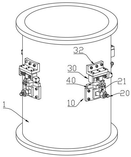
[0034] Such as figure 1 As shown, a nozzle automatic adjustment mechanism applied to a fluidized bed type pulverizer, including: a plurality of mount 10, mounting seat 10, is mounted on the side wall of the fluidized bed 1. The number of seats 10 can be set according to specific crushing requirements, which is easy to implement in those skilled in the art. The mounting seat 10 is used to rotate the fixed nozzle 20, that is, the mount 10, each nozzle 20 is adjustable to the angle of the injective airflow in the fluidized bed 1, and the nozzle can form different jet angles to form different Airflow, thereby meeting different raw material crushing requirements without replacing different fluidized beds.

[0035] Further, the present embodiment further includes a drive mechanism, and the drive mechanism is used to control the nozzle 20, that is, the angle of adjusting the nozzle 20 into the fluidized bed 1, the drive mechanism is fixed to the side wall of the fluidized bed 1.

[0036]...

Embodiment 2

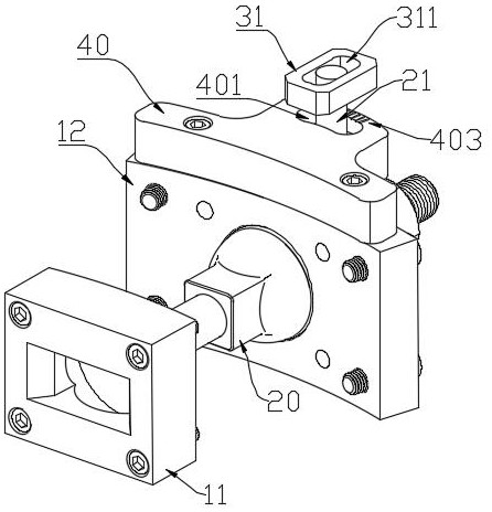
[0038] Of course, there are many structures that can rotate the nozzle 20, but from the reliability of the processes, mounting, and nozzle 20, this example gives a specific drive mechanism, such as figure 2 As shown, in the basis of the first embodiment, the drive mechanism is designed. The drive mechanism of the present embodiment includes a guide bar 21 and a straight moving mechanism 30, and the guide bar 21 is disposed vertically, one end of the guide bar 21. The nozzle 20 is fixed, and the other end of the guide bar 21 is fixed to the linear moving mechanism 30, and the linear moving mechanism 30 is used to generate a horizontal movement to drive the nozzle 20. From figure 2 It can be seen that the guide bar 21, the straight line movement mechanism 30 is provided above the nozzle 20, but from the structure of the structural design, the rotation of the nozzle 20, the guide bar 21, the linear moving mechanism 30 is also provided below the nozzle 20. Viable, does not affect the ...

Embodiment 3

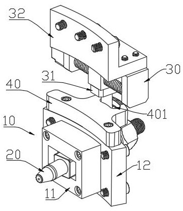
[0042] The present embodiment is the substantially the same, and the present embodiment is, in this embodiment, the mount 10 has been innovative, specifically, such as image 3 , Figure 4 As shown, the mounting seat 10 includes an inner plate 11 and an outer panel 12, and the inner plate 11 is in conjunction with the outer panel 12, and a cylindrical hole is provided at a bonded hole, and the cylindrical hole is divided into two halves. Working with the bonding surface of the outer panel 12, of course, in order to prevent pressure in the fluidized bed, it is necessary to have a gasket or a sealing ring between the inner plate 11 and the outer panel 12, and the nozzle 20 has The cylindrical boss matched the cylindrical hole, and the cylindrical boss rotates into the cylindrical hole, the cylindrical boss is rotated by the nozzle 20, and the inner plate 11 and the outer panel 12 are processed in the circumferential direction of the fluidized bed 1. And the strip hole and the cylindri...


PUM


Abstract

The invention discloses an automatic nozzle adjusting mechanism applied to a fluidized bed type pulverizer, comprising: a plurality of mounting seats for rotatably fixing nozzles, the mounting seats being mounted on the side wall of a fluidized bed; the driving mechanism is used for controlling the nozzle to rotate, and the driving mechanism is fixed on the side wall of the fluidized bed. According to the invention, the angle of the nozzle of the fluidized bed can be adjusted, so that the crushing requirements of particles with different sizes can be met without replacing different fluidized beds, the use efficiency of the fluidized bed and the adaptability to different materials are greatly improved, and the requirements of customers are greatly met.

Description

Technical field [0001] The present invention belongs to the field of airflow pulverization, in particular a nozzle automatic adjustment mechanism applied to fluidized bed pulverizer. Background technique [0002] Fluidized Bed Airflow pulverizer, using a two-dimensional or three-dimensional set of airflow impacts the material to disseminate the material in a fluidized bed suspended. [0003] The existing fluidized bed nozzle is generally installed on the barrel wall of the fluidized bed. The position of the nozzle cannot be adjusted, and a set of fluidized bed can only be used for crushing of the same specification particles. If you want to crush different specifications granules The material needs to replace different fluidized beds, which leads to a large limit. Inventive content [0004] In order to overcome the shortcomings of the prior art, the present invention provides a nozzle automatic adjustment mechanism applied to fluidized bed pulverizer to solve the problem of the ...

Claims


Application Information

Patent Timeline
Patent Type & Authority Applications(China)
IPC IPC(8): B02C19/06B02C23/00
Inventor 熊斌
Owner 熊斌
Why Eureka
Try Eureka