
Die package including encapsulated die and method of manufacturing the same

a technology of encapsulated dies and die packages, which is applied in the direction of electrical equipment, semiconductor devices, semiconductor/solid-state device details, etc., can solve the problems of deteriorating affecting the reliability of die packages, and increasing the production cost of die packages b>10/b>, so as to minimize the occurrence of warpage and improve reliability

Inactive Publication Date: 2010-12-23
SAMSUNG ELECTRO MECHANICS CO LTD
View PDF2 Cites 19 Cited by
  • Summary
  • Abstract
  • Description
  • Claims
  • Application Information

AI Technical Summary

Benefits of technology

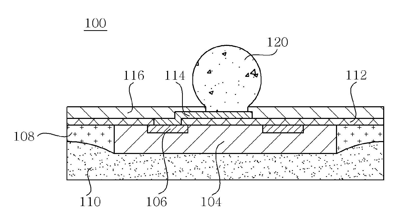
The present invention provides a die package with an encapsulated die that improves reliability by minimizing warping caused by differences in thermal expansion coefficients. The manufacturing process is simple and low-cost. The die package includes a die with pads on one side, an encapsulation layer covering the lateral sides of the die, a support layer covering the encapsulation layer and the other side of the die, a passivation layer formed on the one side of the die such that the pads are exposed, and a redistribution layer formed on the passivation layer such that one part thereof is connected with the pad. The encapsulation layer may be thinner than the die and the support layer may have a lower thermal expansion coefficient than the encapsulation layer. The method of manufacturing the die package includes adhering dies to a tape, forming an encapsulation layer, adding a support layer, removing the tape, and adding a passivation layer and a redistribution layer. The method may also include adding a solder resist layer and an external connecting terminal. The technical effects of the invention include improved reliability, simplified manufacturing process, and lower production cost.

Problems solved by technology

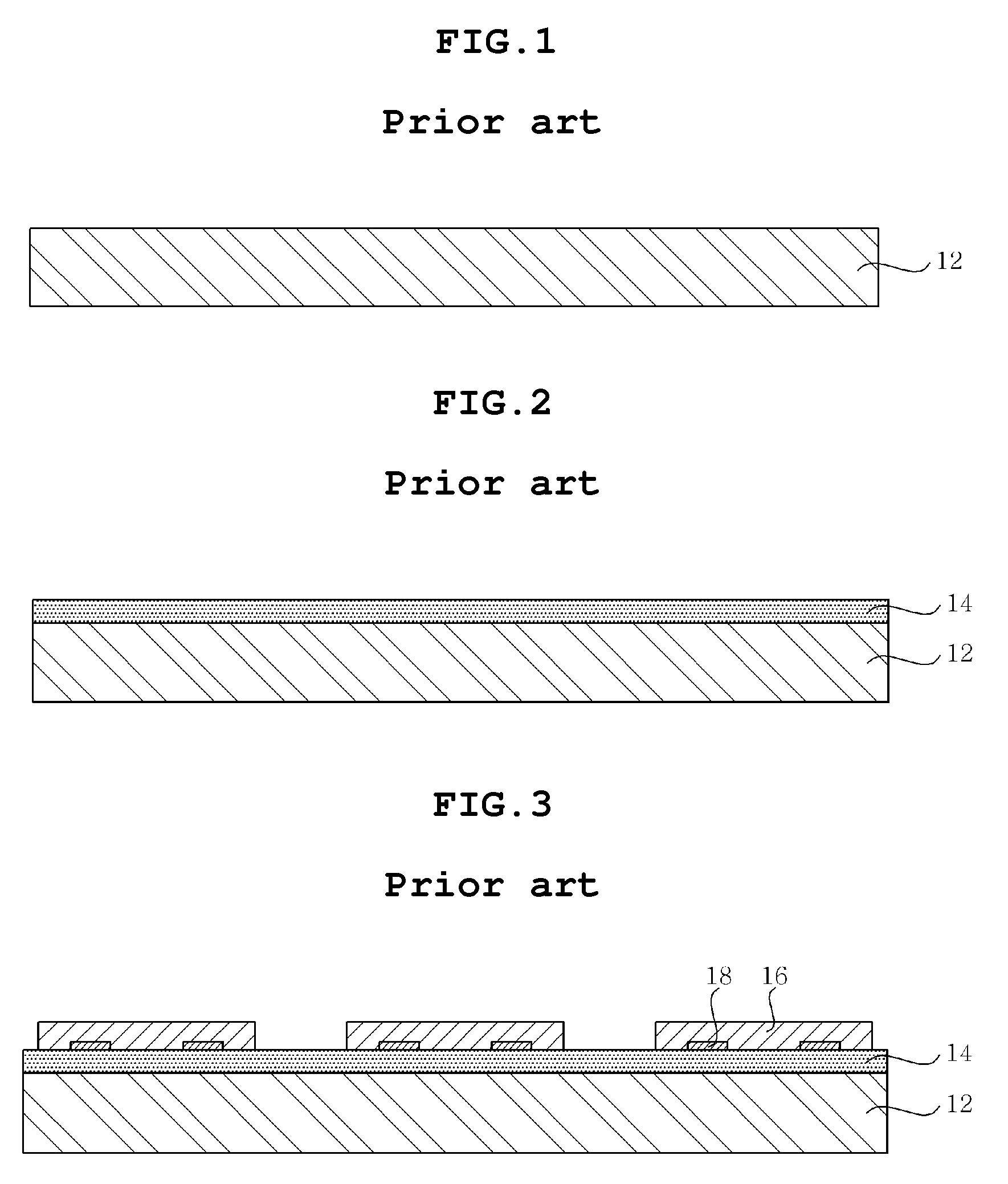
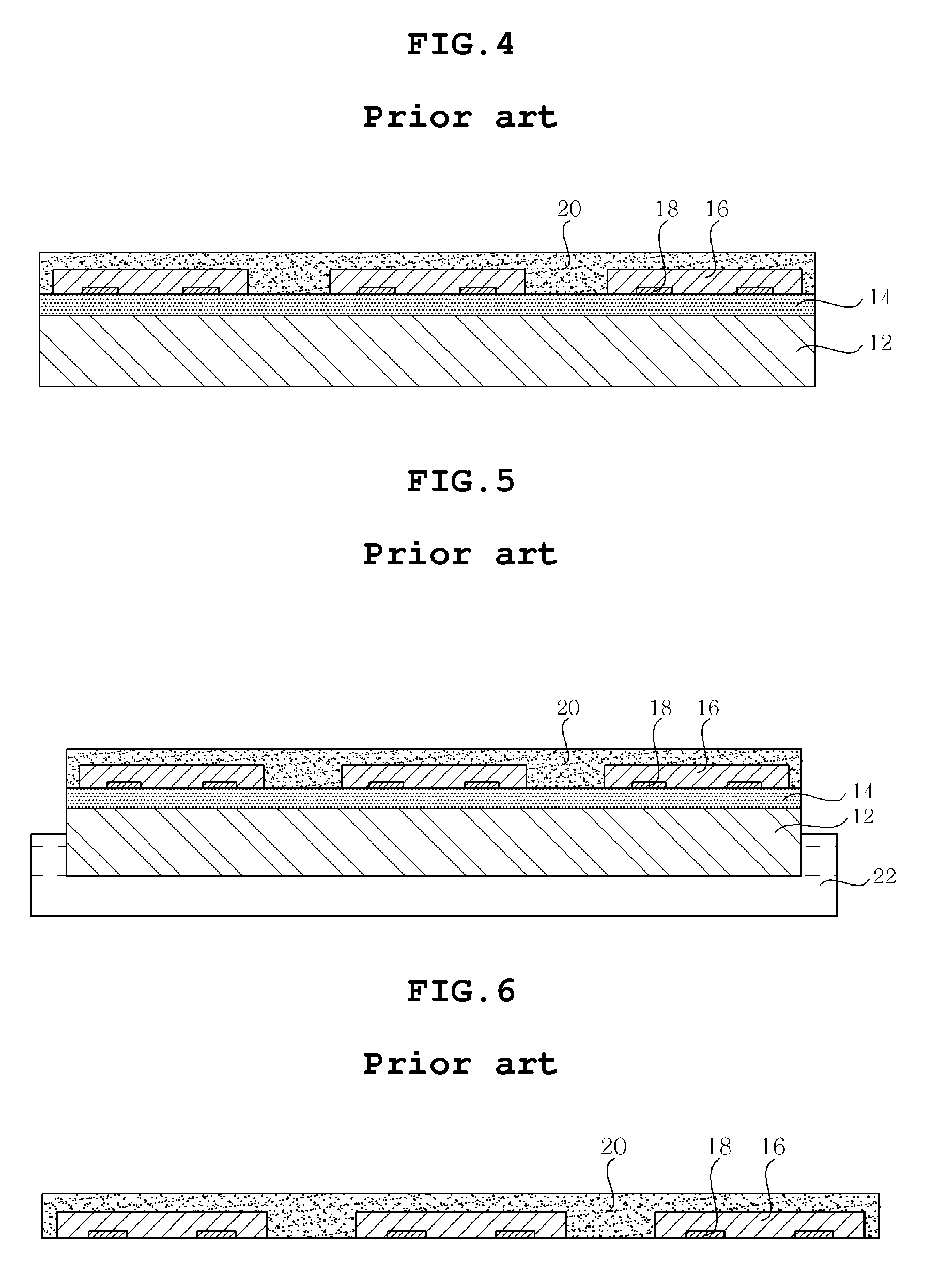
However, the conventional die package 10 is problematic in that the encapsulation layer 20 having a thermal expansion coefficient higher than those of other constituents is formed on both lateral sides and upper sides of the dies, so that the die package 10 warps due to the difference in thermal expansion coefficient between the encapsulation layer 20 and other constituents, thereby deteriorating the reliability of the die package 10.
Moreover, the conventional die package 10 is also problematic in that, since the encapsulation layer 20 is expensive, increasing the amount of material used to form the encapsulation layer 20 increases the production cost of the die package 10.
Furthermore, the conventional die package 10 is problematic in that, since the carrier type porous ceramic plate 12 is used, its manufacturing process is complicated, and its production cost is increased.

Method used


Image

  • Die package including encapsulated die and method of manufacturing the same
  • Die package including encapsulated die and method of manufacturing the same
  • Die package including encapsulated die and method of manufacturing the same

Examples


Embodiment Construction

[0041]The objects, features and advantages of the present invention will be more clearly understood from the following detailed description and preferred embodiments taken in conjunction with the accompanying drawings. Throughout the accompanying drawings, the same reference numerals are used to designate the same or similar components, and redundant descriptions thereof are omitted. In the following description, the terms “first”, “second” and the like are used to differentiate a certain component from other components, but the configuration of such components should not be construed to be limited by the terms. Further, in the description of the present invention, when it is assumed that the detailed description of the related art would obscure the gist of the present invention, the description thereof will be omitted.

[0042]Hereinafter, preferred embodiments of the present invention will be described in detail with reference to the attached drawings.

[0043]Structure of a Die Package...


PUM


Abstract

Disclosed herein is a die package including an encapsulated die, including: a die including pads on one side thereof; an encapsulation layer covering lateral sides of the die; a support layer covering the encapsulation layer and one side of the die; a passivation layer formed on the other side of the die such that the pads are exposed therethrough; and a redistribution layer formed on the passivation layer such that one part thereof is connected with the pad. Here, since one side of the die is supported by the support layer and the encapsulation layer is formed on only the lateral side of the die, the warpage of the die package due to the difference in thermal expansion coefficient can be minimized.

Description

CROSS REFERENCE TO RELATED APPLICATION[0001]This application claims the benefit of Korean Patent Application No. 10-2009-0054396, filed Jun. 18, 2009, entitled “Die package having encapsulated die and method of manufacturing the same”, which is hereby incorporated by reference in its entirety into this application.BACKGROUND OF THE INVENTION[0002]1. Technical Field[0003]The present invention relates to a die package including an encapsulated die and a method of manufacturing the same.[0004]2. Description of the Related Art[0005]With the advancement of the electronics industry, electronics parts have been gradually becoming highly-functionalized and miniaturized. Thus, next-generation multi-functional small-sized packages having more functions in a limited area have attracted considerable attention, and, particularly, the development of a die package provided therein with an electronic part (a die) has attracted considerable attention.[0006]In particular, recently, a die package incl...

Claims


Application Information

Patent Timeline
Patent Type & Authority Applications(United States)
IPC IPC(8): H01L23/28H01L23/522H01L21/56H01L21/50
CPCH01L21/568H01L2924/01033H01L23/3171H01L23/5389H01L24/19H01L24/96H01L2224/04105H01L2224/20H01L2924/01002H01L2924/01013H01L2924/01029H01L2924/01047H01L2924/01079H01L2924/14H01L2924/15311H01L2924/01005H01L2924/01006H01L23/3107H01L2924/181H01L2924/3511H01L2924/00H01L23/28
Inventor KANG, JOON SEOKKWEON, YOUNG DOKIM, HONG WONYUAN, JINGLI
Owner SAMSUNG ELECTRO MECHANICS CO LTD
Learn More