
Systems and Methods for Variable Rate Conversion

a variable rate conversion and rate converter technology, applied in pulse conversion, amplitude demodulation, instruments, etc., can solve the problems of reducing the sampling rate of input and outpu

Active Publication Date: 2010-12-23
SYNAPTICS INC
View PDF11 Cites 47 Cited by
  • Summary
  • Abstract
  • Description
  • Claims
  • Application Information

AI Technical Summary

Benefits of technology

[0020]An alternative to straight interpolation is to skip the interpolation when the fractional part, that is the difference between the phase offset and the largest phase index less than the phase offset, is near zero. A small fraction approximator can be used which uses the result of the poly-phase f

Problems solved by technology

One difficulty with this approach is that it relies on finding a reasonable least common multiple.
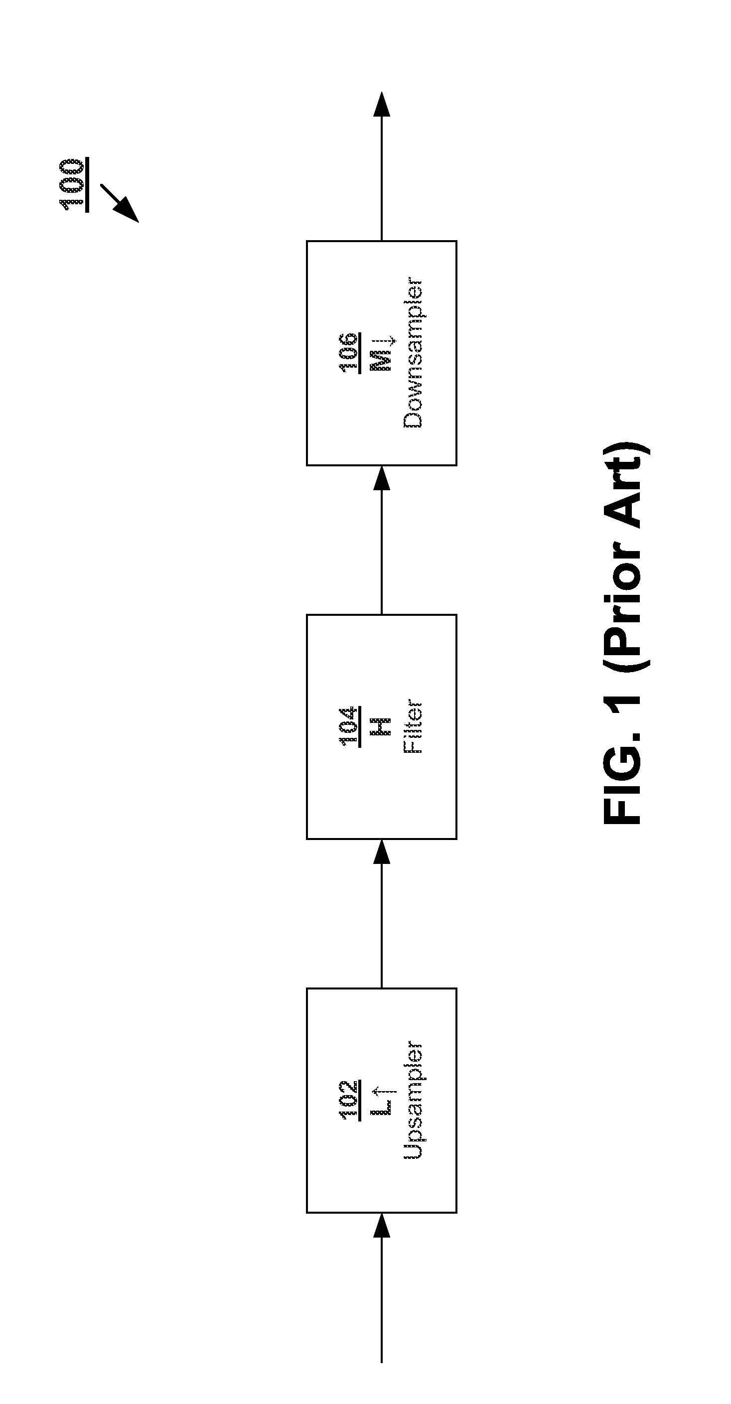
One key challenge is that the low pass filter would have to operate at 7.056 Mhz which is more than 100 times the sampling rate either input or output operate at.
The difficulty in this particular design in a rate converter not only is in the size of the filter, but the delay lines, scaling elements, and adders must operate at the high common multiple sampling rate.
This could drastically increase the cost of the components.
One difficulty with the traditional use of poly-phase filters is that the design relies on a fixed input and output sampling rate.
It is not suitable for changing rates.
In the case of an incommensurate ratio between sampling rates, the traditional poly-phase rate converter cannot be applied.
The primary difficulty in this approach is that it has high computational load and it is inflexible because the filter coefficients for all the filters must be calculated offline beforehand.
In particular, it does not allow flexibility in tradeoff between complexity and quality once the filter coefficients have been designed.

Method used


Image

  • Systems and Methods for Variable Rate Conversion
  • Systems and Methods for Variable Rate Conversion
  • Systems and Methods for Variable Rate Conversion

Examples


Embodiment Construction

[0061]A detailed description of embodiments of the present invention is presented below. While the disclosure will be described in connection with these drawings, there is no intent to limit it to the embodiment or embodiments disclosed herein. On the contrary, the intent is to cover all alternatives, modifications and equivalents included within the spirit and scope of the disclosure as defined by the appended claims.

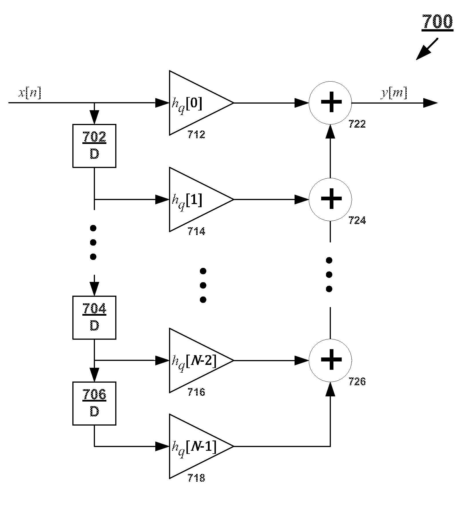
[0062]In a rate converter the discrete low pass filter should have a bandwidth 1 / R where R is typically the larger of the upsampling factor L and downsampling factor M. One implementation of the low pass filter has an impulse response of h[n]=W[n].

sinc(nR),

where W[n] is a impulse response of a window function. When this is split into poly-phase filter components

hm[k]=h[L·k+m]=W[L·k+m]·sinc(LRn+mR),(7)

where m is an index based on the output samples and k is an index based on the input samples. Furthermore, the arithmetic inside the brackets of h[] and W[] is performed m...


PUM


Abstract

Poly-phase filters are used to offer an efficient and low complexity solution to rate conversion. However, they suffer from inflexibility and are not easily reconfigured. A novel design for rate converters employ poly-phase filters but utilize interpolation between filter coefficients to add flexibility to rate conversion. This interpolation can be implemented as an interpolation of the poly-phase filter results. Additional approximations can be made to further reduce the amount of calculations required to implement a flexible rate converter.

Description

BACKGROUND OF THE INVENTION[0001]1. Field of the Invention[0002]The present invention relates generally to rate conversion of digital data and specifically with the use of poly-phase filters for rate conversion.[0003]2. Related Art[0004]Data is often manifested as discrete time data, that is a representative sample is presented at a given rate. Digital data goes further and each sample is quantized to a digital value. While some data is derived purely digitally, such as the results from a computation by the process, other data is associated with an original analog form, such as audio or video. The analog signal is sampled at the given rate to convert it to a discrete time or digital data. This rate is known as the sampling rate. For example, in audio applications, 44.1 kHz and 48 kHz are common sampling rates.[0005]The process of converting between two sampling rates is known as rate conversion. If the rate conversion goes from a lower rate to a higher rate, it is referred to as ups...

Claims


Application Information

Patent Timeline
IPC IPC(8): H03M7/00H04L27/06H04L7/00
CPCH03M5/02H03H17/0685H03H17/0642H03H17/0275
Inventor JONSSON, RAGNAR H.THORVALDSSON, VILHJALMUR S.THORMUNDSSON, TRAUSTI
Owner SYNAPTICS INC
Learn More