Receiver for fsk radio frequency signals with high sensitivity demodulator and method for activating the same

Active Publication Date: 2012-06-28
THE SWATCH GRP RES & DEVELONMENT LTD
View PDF6 Cites 21 Cited by
  • Summary
  • Abstract
  • Description
  • Claims
  • Application Information

AI Technical Summary

Benefits of technology

[0009]It is thus an object of the invention to provide an FSK radio frequency signal receiver, which is a high sensitivity receiver and can easily be configured to c

Problems solved by technology

Thus, a broadband transmission or reception system generally does not have excellent sensitivity.
However, even if the intermediate signals provided by the mixer unit are immediately subjected to lowpass or bandpass filtering, this does not allow precise filtering to be subsequently performed to obtain a high sensitivity receiver.
In these conditions, the data or commands in the incoming radio frequency signals cannot all be extracted after the demodulation stage, which is a d

Method used


Image

  • Receiver for fsk radio frequency signals with high sensitivity demodulator and method for activating the same
  • Receiver for fsk radio frequency signals with high sensitivity demodulator and method for activating the same
  • Receiver for fsk radio frequency signals with high sensitivity demodulator and method for activating the same

Examples


first embodiment

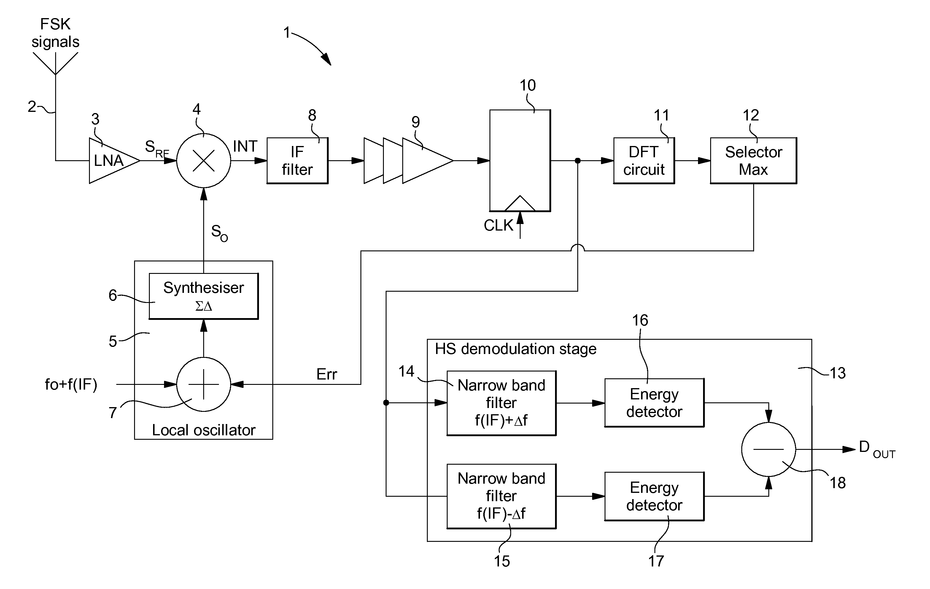
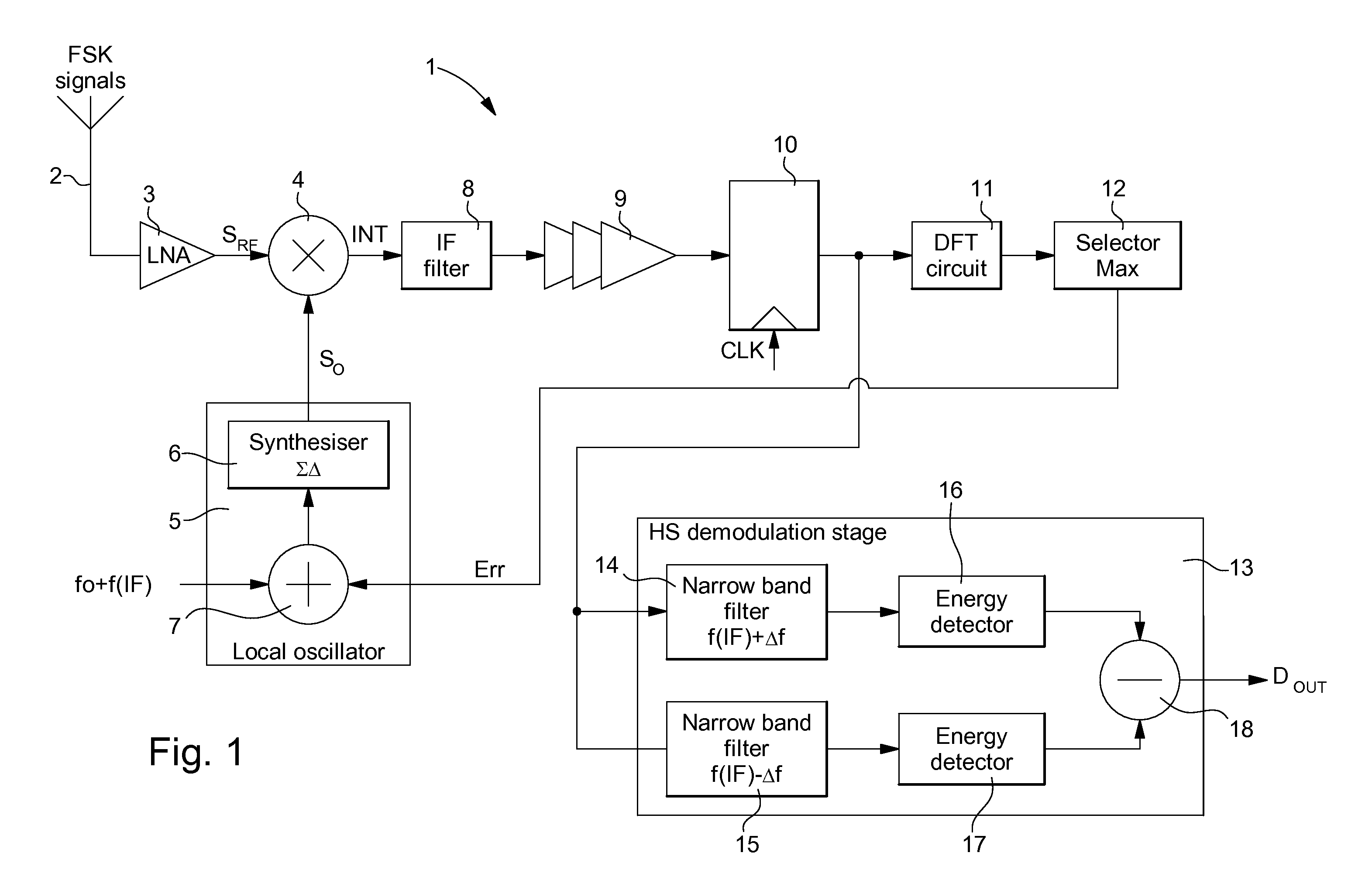
[0056]In the first embodiment shown in FIG. 1, the HS demodulation stage 13 performs high sensitivity demodulation once the frequency of the intermediate signals has been properly adapted. This HS demodulation stage 13 includes a first narrow band digital filter 14 for filtering the sampled intermediate signals having a positive frequency deviation f(IF)+Δf, and a second narrow band digital filter 15 for filtering the sampled intermediate signals having a zero or negative frequency deviation f(IF)−Δf. The bandwidth of each digital filter may be on the order of 2 kHz. The filtered signals at the output of the first digital filter 14 pass through a first energy detector 16, whereas the filtered signals at the output of the second digital filter 15 pass through a second energy detector 17. A subtractor 18 is also provided at the output of detectors 16, 17 so that the signals at the output of the second energy detector 17 are subtracted from the signals at the output of the first energy...

second embodiment

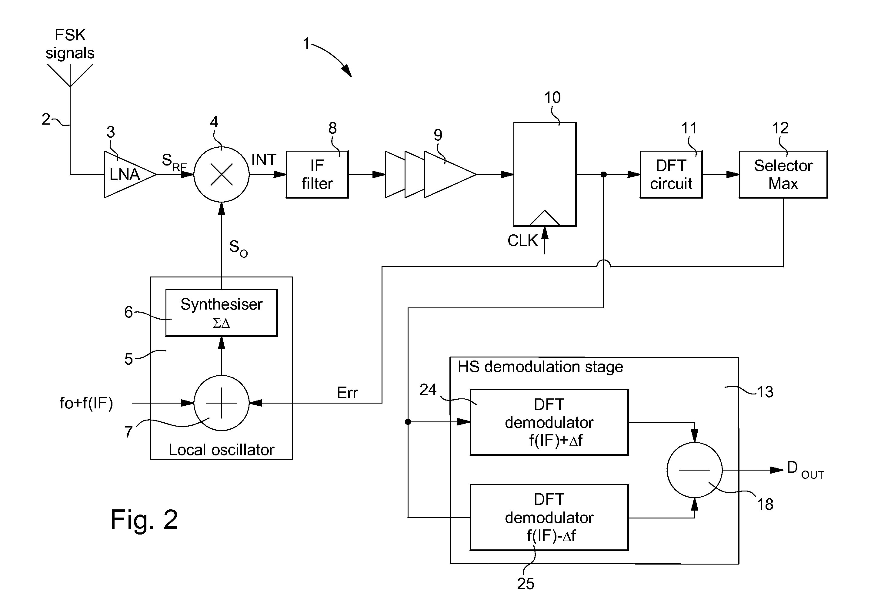
[0057]In the second embodiment shown in FIG. 2, HS demodulation stage 13 includes a first DFT demodulator 24 for demodulating the sampled intermediate signals having a positive frequency deviation f(IF)+Δf, and a second DFT demodulator 25 for demodulating the sampled intermediate signals having a zero or negative frequency deviation f(IF)−Δf. The two DFT demodulators perform a well known sliding discrete Fourier transform with a number of bands reduced to single units within the frequency range of 2 kHz for example. The signals at the output of the second DFT demodulator 25 are subtracted in a subtractor 18 from the signals at the output of the first DFT demodulator 24, so as to provide data or command signals DOUT.

[0058]FIG. 4 shows a flow chart of the method of activating the high sensitivity FSK radio frequency signal receiver according to the invention. A first phase of the method consists in checking the frequency of the intermediate signals, following frequency conversion of t...


PUM


Abstract

The high sensitivity FSK radiofrequency signal receiver includes an antenna for receiving FSK radiofrequency signals, a LNA amplifier receiving signals picked up by the antenna, a local oscillator for supplying oscillating signals, a mixer for mixing the incoming signals with the oscillating signals to produce intermediate signals. The receiver includes a broadband or poly-phase filter for filtering the intermediate signals, and a sampler for supplying sampled intermediate signals to a high sensitivity demodulation stage, which supplies data signals. The receiver includes a processing circuit for performing a discrete Fourier transform of sampled intermediate signals. The selector at the processing circuit output determines the difference between the signal amplitude peak frequency above a determined threshold and the expected frequency of the intermediate signals. The frequency difference enables for correcting the oscillating signals frequency, to enable the demodulation stage to demodulate the data in the sampled intermediate signals and supply data signals.

Description

[0001]This application claims priority from European Patent Application No. 10196893.1 filed Dec. 23, 2010, the entire disclosure of which is incorporated herein by reference.FIELD OF THE INVENTION[0002]The invention concerns a receiver for FSK radio frequency signals with a high sensitivity demodulator.[0003]The invention also concerns a method of activating the receiver for FSK radio frequency signals with a high sensitivity demodulator.BACKGROUND OF THE INVENTION[0004]For data or command transmission or reception, for example within a short range, a conventional transmitter or receiver uses frequency shift keying. If the RF carrier frequency is high, for example on the order of 2.4 GHz, a relatively high bandwidth is selected for the intermediate frequency, in particular, higher than or equal to 200 kHz. The modulation frequency deviation in the modulated signals can be adapted according to the bandwidth. In such case, a frequency reference may be used, provided by a local oscill...

Claims


Application Information

Patent Timeline
IPC IPC(8): H04B1/16
CPCH04L27/14
Inventor CASAGRANDE, ARNAUDAREND, JEAN-LUC
Owner THE SWATCH GRP RES & DEVELONMENT LTD
Why Eureka
Try Eureka