Image enlargement apparatus, method, integrated circuit, and program

a technology of image enlargement and apparatus, applied in the field of image enlargement methods, can solve the problems of affecting overshooting or undershooting, and image quality degradation, and achieve the effect of enlargement process

Active Publication Date: 2010-12-23
PANASONIC CORP
View PDF31 Cites 29 Cited by
  • Summary
  • Abstract
  • Description
  • Claims
  • Application Information

AI Technical Summary

Benefits of technology

[0038]First, according to the present invention, a portion where overshoot or undershoot occurs in an edge portion because the correction amount calculated by the correction amount calculation unit is excessively large can be adjusted again, so that a sharp, natural enlarged image with little shoot can be generated.
[0039]Moreover, according to the present invention, a visual phenomenon that white appears thicker as a result of an edge sharpening process in an enlargement process can be suppressed.

Problems solved by technology

However, these methods have the following drawbacks.
This being so, when an enlargement factor increases, visual blocks become noticeable and cause degradation in image quality.
When edge enhancement is performed, however, an artifact called overshoot or undershoot occurs near an edge in the image.
Thus, when performing the edge enhancement by the high-pass enhancement filter, though a sharp image is obtained, there is also an adverse effect that the image has visual degradation as a neighborhood of an edge in the image appears bright.

Method used


Image

  • Image enlargement apparatus, method, integrated circuit, and program
  • Image enlargement apparatus, method, integrated circuit, and program
  • Image enlargement apparatus, method, integrated circuit, and program

Examples


embodiment a

[0101]The following describes the embodiment A with reference to drawings. Note that the embodiment A includes embodiments A1 and A2.

embodiment a1

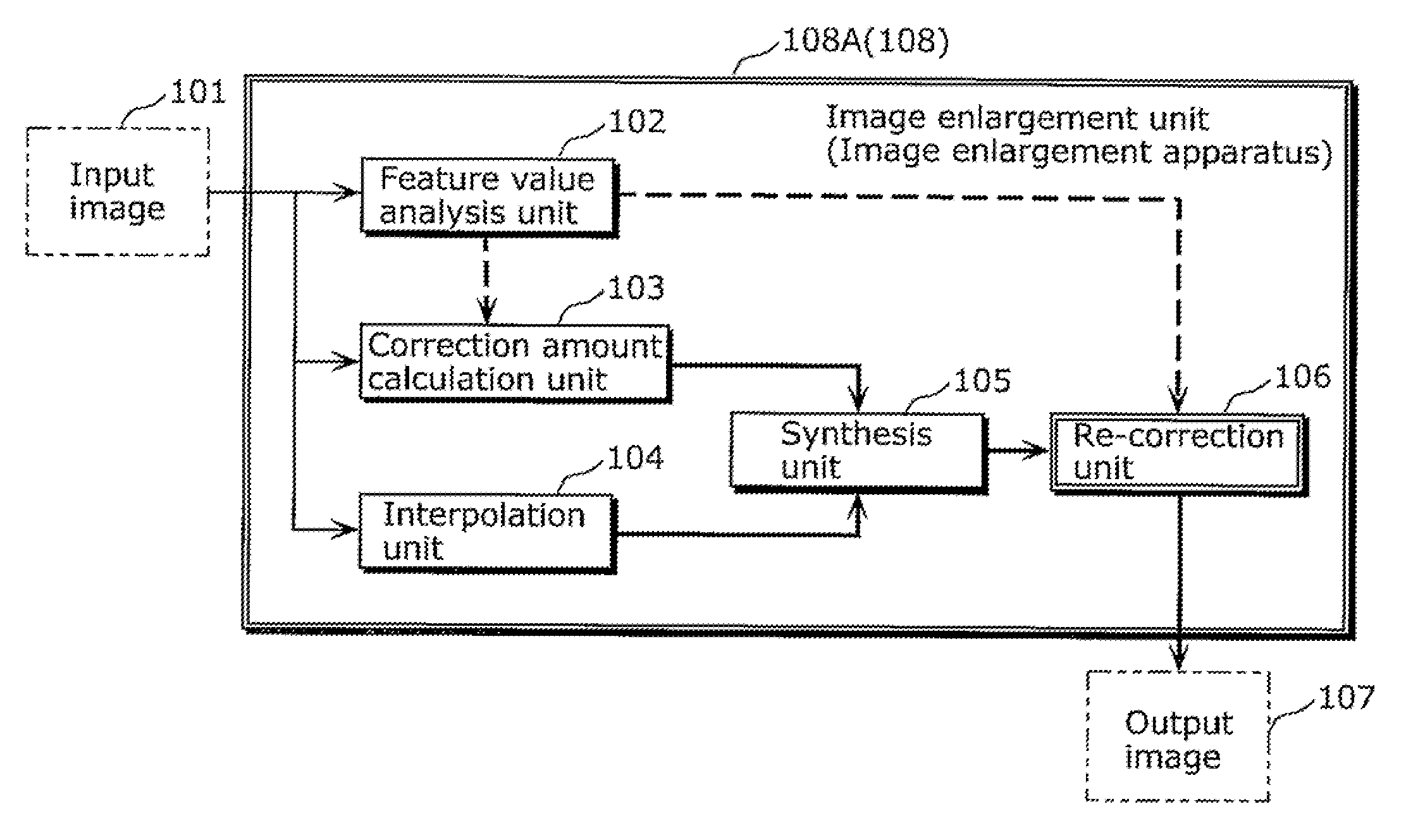
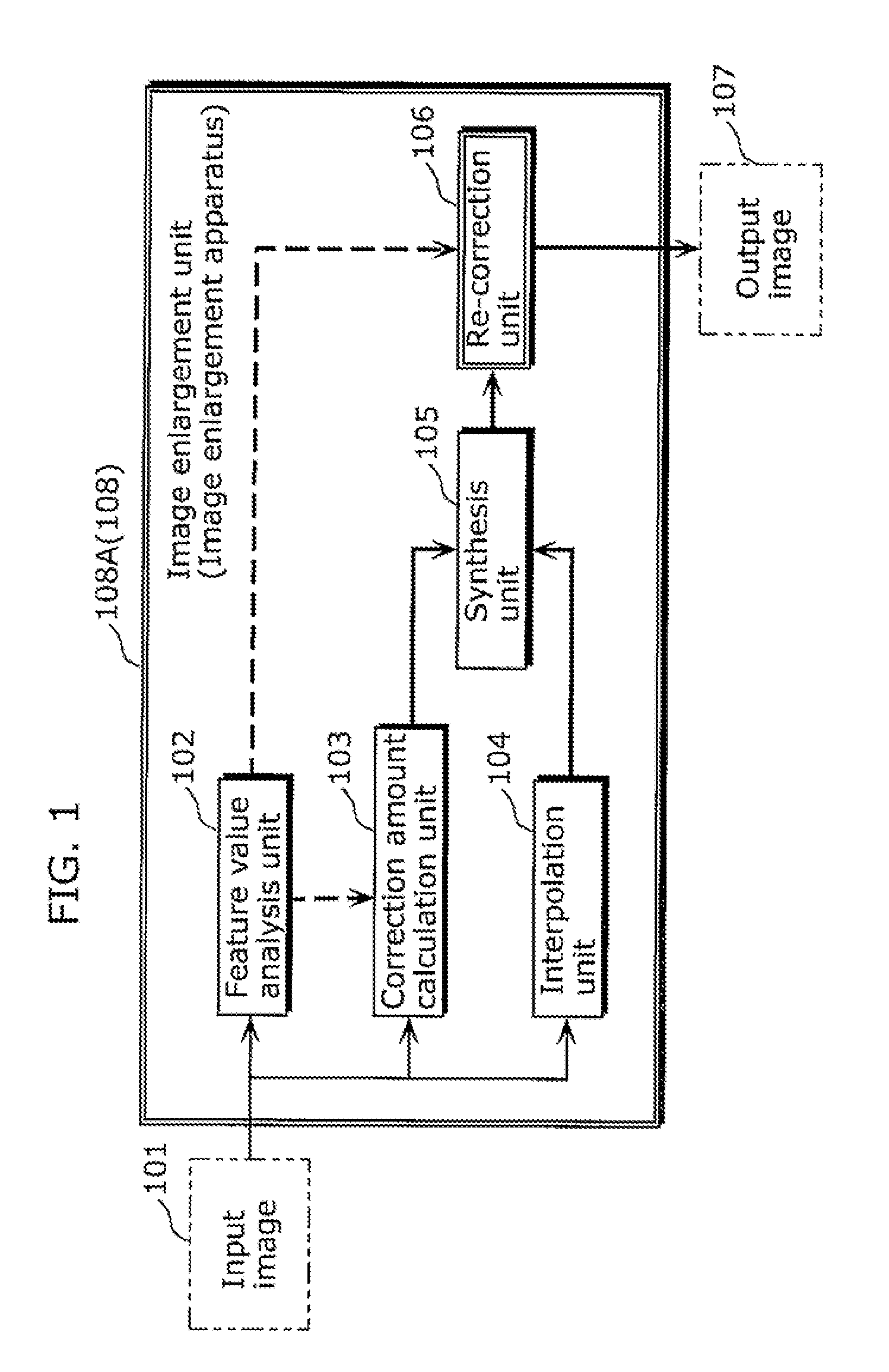
[0102]FIG. 1 is a block diagram of an image enlargement unit (image enlargement apparatus) 108A in the embodiment A1.

[0103]Note that the image enlargement unit 108A is a subordinate conception of the image enlargement apparatus 108 (mentioned above).

[0104]In FIG. 1, 101 denotes a low-resolution input image (original image, low-resolution image). 102 denotes a feature value analysis unit that outputs a feature value corresponding to each pixel of a high-resolution image (output image, second high-resolution image) 107 outputted from the image enlargement unit 108A, from the low-resolution input image. 103 denotes a correction amount calculation unit that calculates a correction amount of an edge component according to the feature value outputted from the feature value analysis unit 102, that is, calculates a correction amount of each pixel of the outputted high-resolution image 107, and outputs the calculated correction amount. 104 denotes an interpolation unit that receives the low-...

embodiment a2

[0173]The following describes the embodiment A2 with reference to drawings.

[0174]FIG. 15 is a block diagram of an image enlargement apparatus 1500 in the embodiment A2.

[0175]In FIG. 15, 101 denotes an input image. 1501 denotes an interpolation position x,y. 1502 denotes a pixel selection unit that selects neighboring 6×6 pixels of the interpolation position x,y 1501. 1503 denotes a decimal position calculation unit that extracts a decimal part px,py of the interpolation position x,y 1501. 1504 denotes an image enlargement unit that receives the 6×6 pixels of the input image and the decimal position px,py, calculates a pixel value of the interpolation position x,y 1501, and outputs the calculated pixel value. 107 denotes a high-resolution image after an enlargement process.

[0176]Note that the image enlargement apparatus 1500 is also a subordinate conception of the image enlargement apparatus 108 (mentioned above). The image enlargement unit 1504 is a superordinate conception of an im...


PUM


Abstract

An image enlargement apparatus (108) includes: an interpolation unit (104 and the like) that generates a high-resolution interpolation image (OL) from a low-resolution image (101); a synthesis unit (105) that generates a first high-resolution image (FIG. 11B, alternate long and short dash line data in a lower part of FIG. 45, and the like) by synthesizing the interpolation image and a correction amount; and a re-correction unit (106) that generates a second high-resolution image (FIG. 11D, solid line data in the lower part of FIG. 45, and the like) by re-correcting the first high-resolution image using a generated feature value.

Description

TECHNICAL FIELD[0001]The present invention relates to an image enlargement method performed by an apparatus that converts a low-resolution image to a high-resolution image, such as a display apparatus that enlarges an inputted low-resolution image according to a resolution of a display device, an image output apparatus such as a printer that enlarges a low-resolution image and outputs the enlarged image, and an imaging apparatus that enlarges an image included in a moving image to generate a still image.BACKGROUND ART[0002]Conventionally, various methods have been proposed as interpolation enlargement techniques of converting an inputted low-resolution image to a high-resolution image. NPL 1 discloses representative techniques including a nearest neighbor method, a bilinear method, and a bicubic convolution method. In the nearest neighbor method, an interpolation pixel value is determined by selecting a low-resolution pixel nearest an interpolation pixel position. In the bilinear me...

Claims


Application Information

Patent Timeline
Patent Type & Authority Applications(United States)
IPC IPC(8): G06K9/32
CPCG06T3/00G09G5/00G09G2320/0242G09G2340/0407H04N7/0142H04N7/012H04N7/0125H04N7/0135H04N1/40068
Inventor TEZUKA, TADANORI
Owner PANASONIC CORP
Why Eureka
Try Eureka