Four-channel transverse dual rotor helicopter

a dual-rotor helicopter and transverse technology, applied in the field of telecontrol aeromodelling control, can solve the problems of difficult control, comparatively complicated mechanical structure controlling the rotor wing angle, and complicated flight operation of the transverse dual-rotor helicopter, so as to simplify the mechanical structure, reduce production costs, and simplify the operation

Inactive Publication Date: 2010-12-23
SHENZHEN ART TECH RC HOBBY
View PDF7 Cites 7 Cited by
  • Summary
  • Abstract
  • Description
  • Claims
  • Application Information

AI Technical Summary

Benefits of technology

[0013]In the present invention, the helicopter rotor wings have only two angle variations of inclining forward or inclining backward, and the helicopter is controlled to fly forward, fly backward or change flight direction by inclining the rotor wing forward or backward. The ascending and descending of the model helicopter are controlled by simultaneously increasing or decreasing the rotation speeds of the motors at the two sides; the inclining of the helicopter is controlled by controlling the variation of the reaction torques via controlling the rotation speeds of the two motor,...

Problems solved by technology

Generally, the fixed wing model aircraft is made comparatively easy to control because of the structure of the type of aircraft, so every people with ordinary response speed can deal with it; and a dual rotor helicopter has more control surfaces, so that the complicated flight operation of a transverse dual rotor helicopter is hard to control without a lot of exercises and the help of electronic devices.
To control an existing transverse dual rotor helicopter to finish various attitudes, changing the rotor wing angle is required by all, so that it is comparatively hard to con...

Method used


Image

  • Four-channel transverse dual rotor helicopter
  • Four-channel transverse dual rotor helicopter
  • Four-channel transverse dual rotor helicopter

Examples


Embodiment Construction

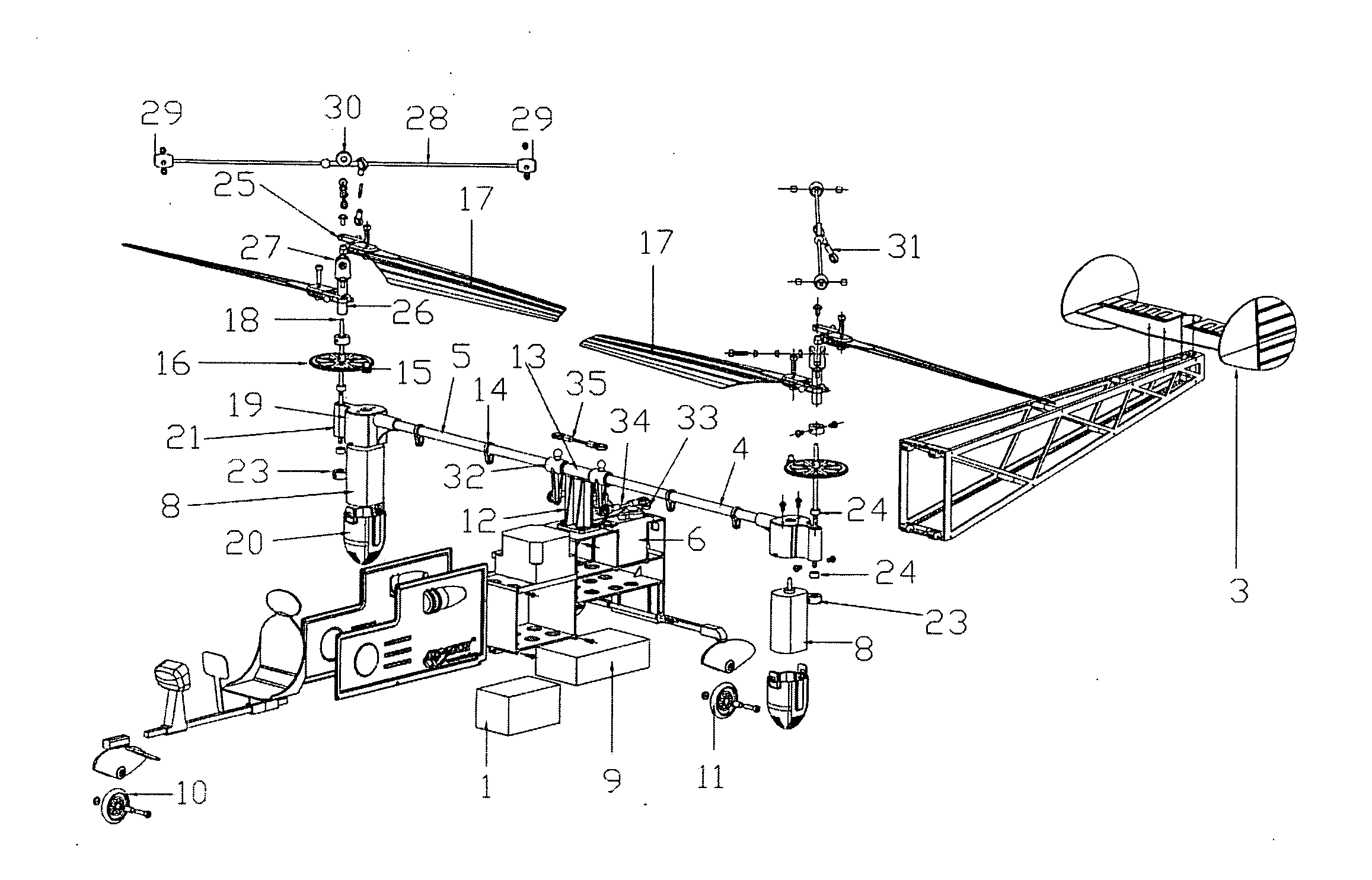
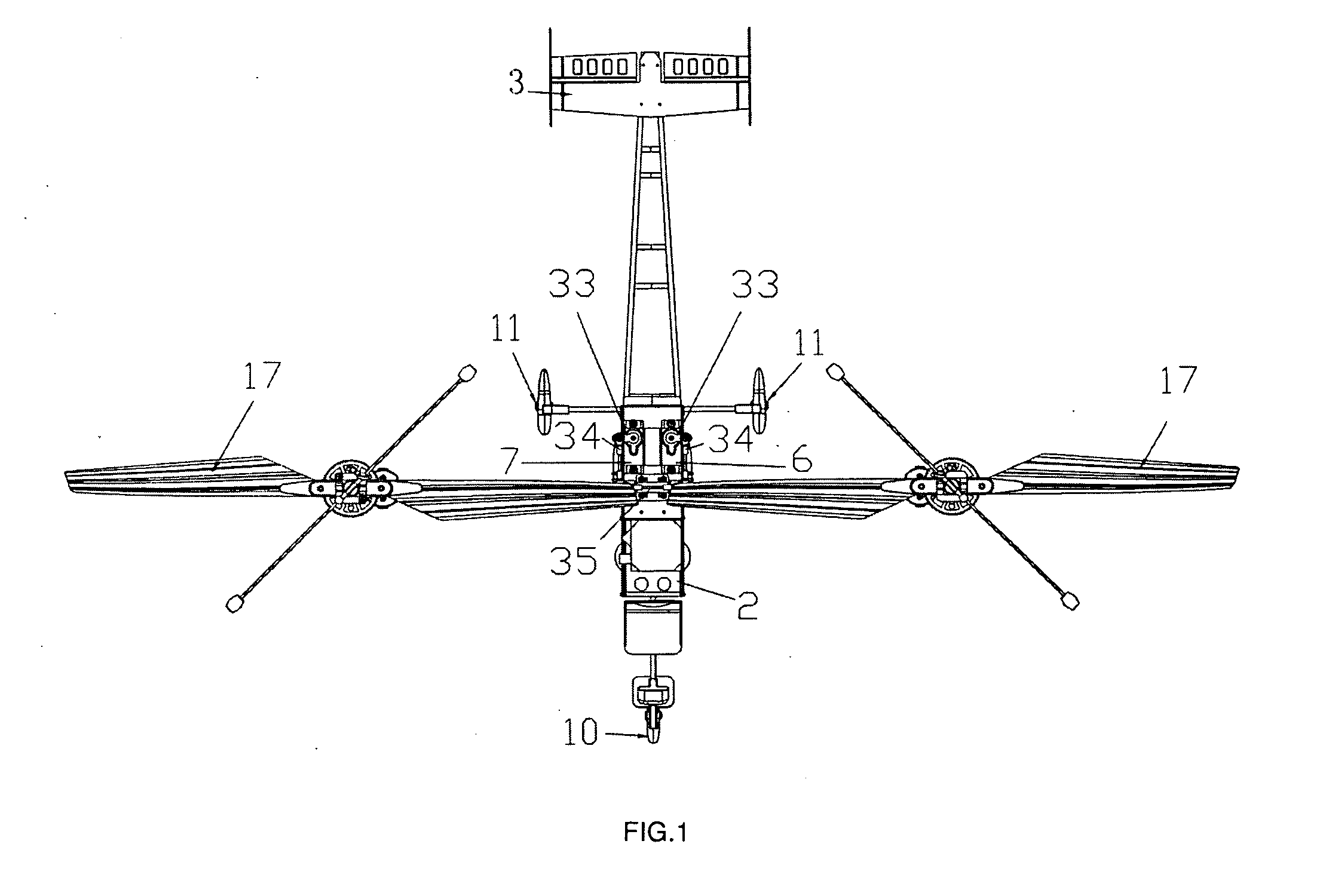
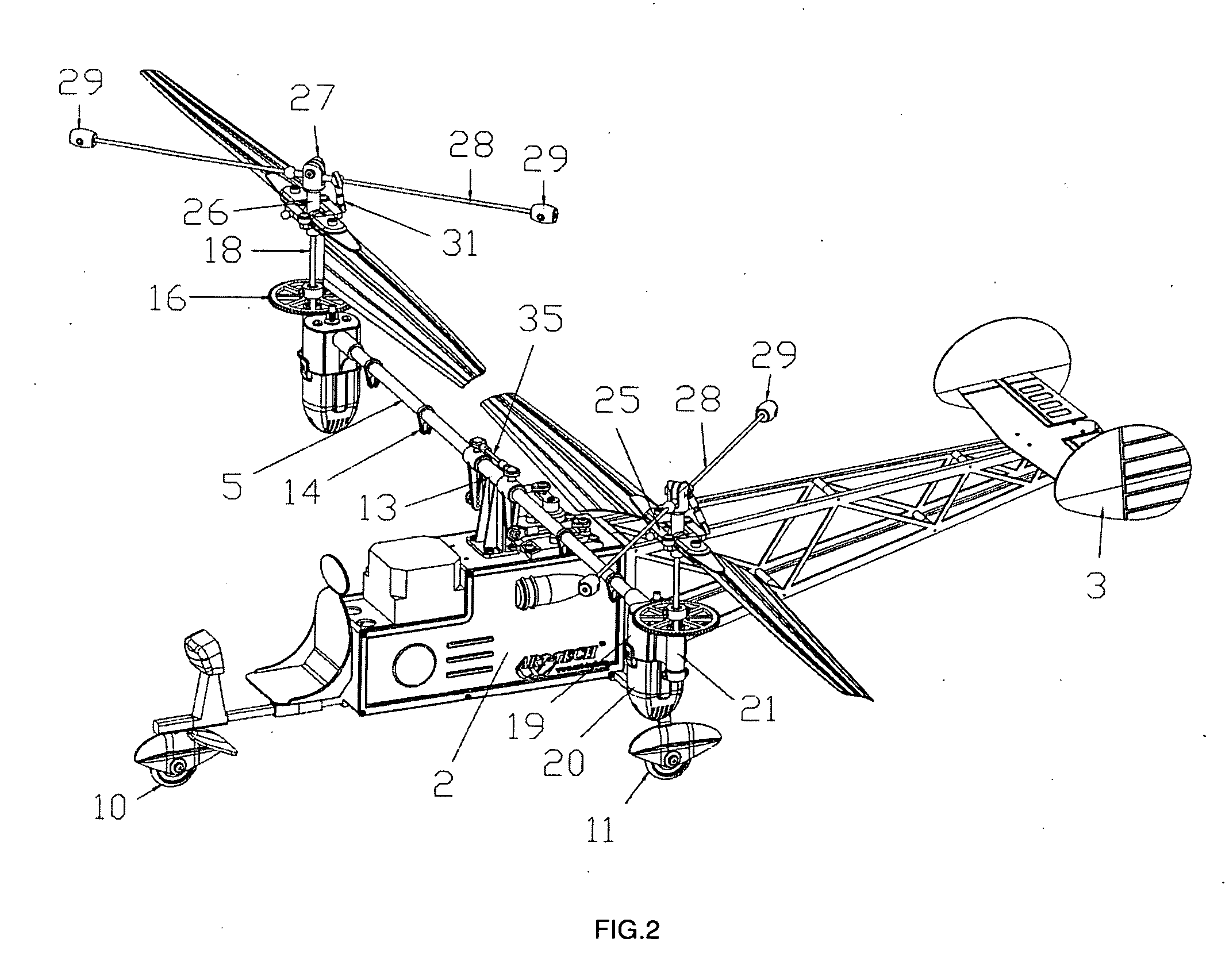
[0017]FIG. 1, FIG. 2 and FIG. 3 are schematic diagram of the basic structure of a preferred embodiment of the present invention. A four-channel transverse dual rotor helicopter comprises a frame 2 with a battery 1 encapsulated inside it, an empennage 3 breadthwise fixed at the afterbody of the frame 2, an aircraft wheel assembly fixed at the bottom of the frame 2, two cantilever bars 4, 5 of left and right connected to the frame 2 being breadthwise fixed at the two sides of the frame 2 and capable of rotating around axes of themselves. The left and right cantilever bars 4, 5 are separately via a group of linkage mechanism connected to left and right steering engines 6, 7 fixed to the frame 2 for driving the left and right cantilever bars 4, 5 to rotate around axes of themselves; the ends of the left and right cantilever bars 4, 5 are separately provided with a group of rotor wing mechanism; the motors 8 of the two groups of rotor wing mechanism and the left and right steering engine...


PUM


Abstract

The present invention provides a four-channel transverse dual rotor helicopter, comprising a frame with a battery encapsulated inside it, an empennage breadthwise located at the afterbody of the frame, an aircraft wheel assembly fixed at the bottom of the frame, wherein, two cantilever bars of left and right are connected to the frame, breadthwise located at the two sides of the frame, and capable of rotating around axes of themselves; the left and right cantilever bars are separately via a group of linkage mechanism connected to left and right steering engines located at the frame for driving the left and right cantilever bars to rotate around axes of themselves; the ends of the left and right cantilever bars are separately provided with a group of rotor wing mechanism; the motors in the two groups of rotor wing mechanism, and the left and right steering engines are connected to a signal receiver located in the frame; the motors are variable speed motors. The present invention is easy to control, so as to make the beginner without controlling foundation also capable of controlling the helicopter to fly stably. At the same time, the simplified mechanical structure of the helicopter reduces the production cost, also greatly improves the performance stability of the helicopter.

Description

BACKGROUND OF THE INVENTION[0001]The present invention relates to technical field of telecontrol aeromodelling control, especially relates to a structure of four-channel transverse dual rotor helicopter.[0002]Currently, the transverse dual rotor helicopter of telecontrol aeromodellings is a vertically rising and falling device using rotor wings as its main lift force source, and is different from the fixed wing model aircraft. Generally, the fixed wing model aircraft is made comparatively easy to control because of the structure of the type of aircraft, so every people with ordinary response speed can deal with it; and a dual rotor helicopter has more control surfaces, so that the complicated flight operation of a transverse dual rotor helicopter is hard to control without a lot of exercises and the help of electronic devices.[0003]To control the flight attitude of a transverse dual rotor helicopter, normally changing the angle of the rotor wings at the two sides is adopted; general...

Claims


Application Information

Patent Timeline
IPC IPC(8): A63H27/127
CPCA63H27/12
Inventor LIANG, JINJINHONG, FANYAO, YONGLIANGLUO, FANGRUI
Owner SHENZHEN ART TECH RC HOBBY
Why Eureka
Try Eureka