Adjustable splinting device

a splinting device and adjustable technology, applied in the field of splinting devices, can solve problems such as heel pain, and achieve the effects of low load, easy gauge and monitor progress, and increased complian

Inactive Publication Date: 2010-12-23
DARCO INT
View PDF11 Cites 50 Cited by
  • Summary
  • Abstract
  • Description
  • Claims
  • Application Information

AI Technical Summary

Benefits of technology

[0007]The present invention provides a dorsiflexion stretch to help relieve symptoms of plantar fasciitis or provide a low load stretch to the Achilles tendon and calf muscles after post-op immobilization. The present invention allows patients to begin with a gradual stretch and progress as the condition improves and compliance is increased. The degree of stretch can be controlled to provide a tolerable stretch force all night. The device allows a patient to easily gauge and monitor progress. The device enhances safety and comfort during nighttime ambulation due to the articulating foot piece and soft bottom.

Problems solved by technology

It is a common cause of heel pain and is sometimes called heel spur.

Method used


Image

  • Adjustable splinting device
  • Adjustable splinting device
  • Adjustable splinting device

Examples


Embodiment Construction

[0022]Illustrative, non-limiting embodiments of the present invention will now be described more fully with reference to the accompanying drawings.

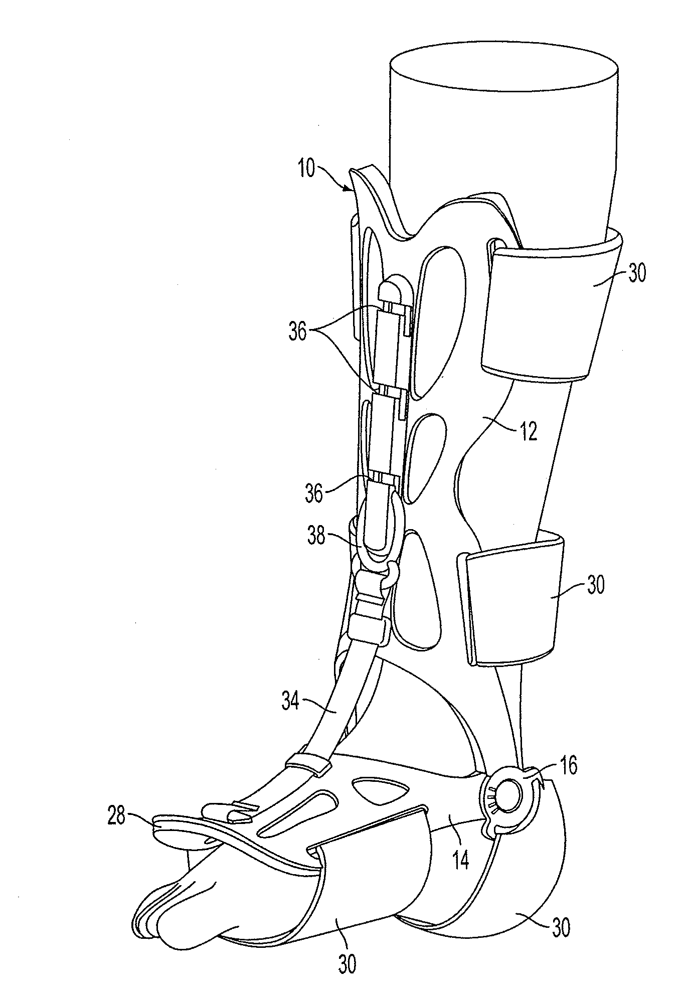
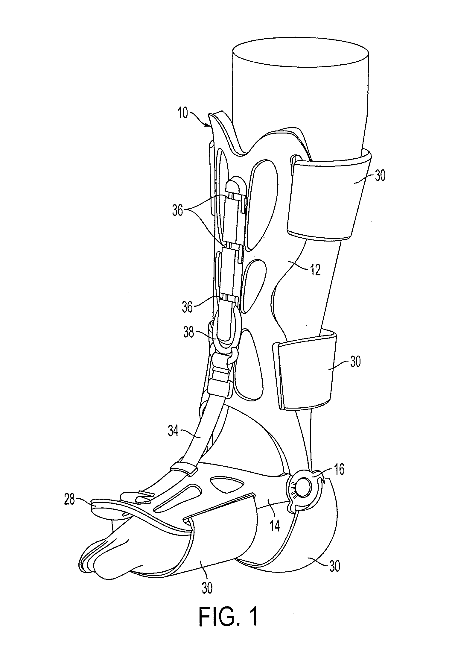
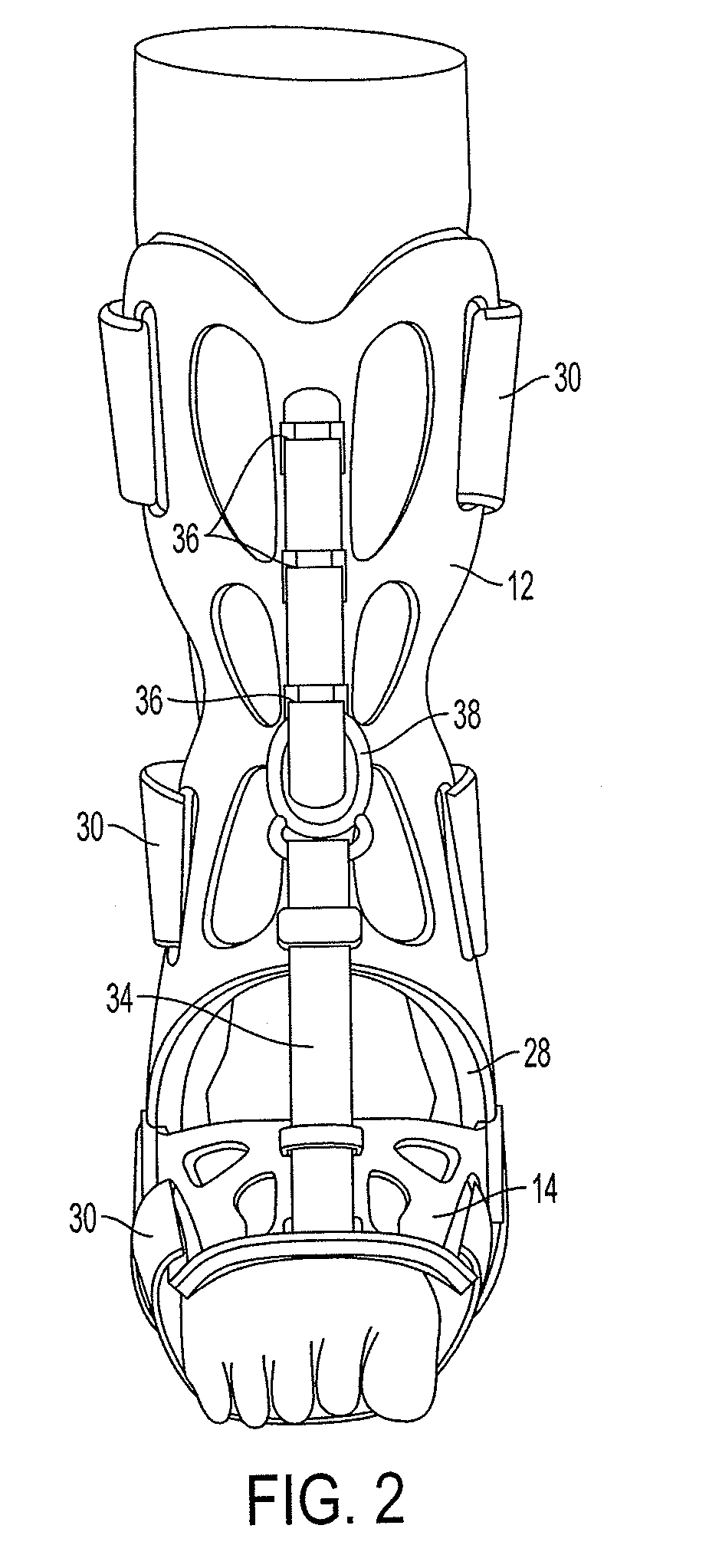
[0023]The splinting device includes a dorsal shell 10 having a first upper part 12 that extends along a shin, i.e., the tibial bone, of a user and a second foot part 14 that extends along the top of the foot, i.e., the cuneiform bone, of a user, as illustrated in FIGS. 1-3. In one exemplary embodiment, the first part 12 and the second part 14 may be one integral shell that is flexible at the location 16 where the first part 12 meets the second part 14, as shown in FIGS. 12 and 13. The first part 12 and the second part 14 may be two separate pieces rotatably or pivotally connected to one another at two pivot points or hinges 16, as shown in FIGS. 1-10.

[0024]Each of the hinges 16 is located at one side of the ankle of the user. The hinge 16 includes a projection 18 on one of the first part 12 and the second part 14, and a through hole 20 th...


PUM


Abstract

A splinting device includes a first part for contacting a lower leg and a second part for contacting a foot hingedly connected to the first part. An adjustable attachment includes an elastic part and interconnects the first part and the second part. A method of treating plantar fasciitis includes securing the first part of the splint device to the lower leg, and securing the second part to a foot. The first part is rotated relative to the second part to establish a predetermined angle between the first part and the second part. The elastic part of the adjustable attachment, which is attached to one of the first and second parts, is stretched and attached to the other of the first part of the second part at a position based on the predetermined angle to limit movement of the first part relative to the second part beyond the predetermined angle.

Description

CROSS-REFERENCE TO RELATED APPLICATION[0001]This application claims priority from U.S. Provisional Patent Application No. 61 / 187,852, filed on Jun. 17, 2009, in the U.S. Patent & Trademark Office, the disclosure of which is incorporated by reference in its entirety.BACKGROUND AND RELATED ART[0002]1. Field of the Invention[0003]Illustrative, non-limiting embodiments of the present invention relate generally to splinting devices, and more particularly to splinting devices for the ankle and lower leg.[0004]2. Background of the Invention[0005]Plantar fasciitis is a painful condition affecting the bottom of the foot. It is a common cause of heel pain and is sometimes called heel spur. A night splint can be worn while you sleep. The night splint keeps your foot from bending downward, and it places a mild stretch on the calf muscles and the plantar fascia. People seem to get better more quickly when using a night splint and they report having less heel pain when placing their sore foot on ...

Claims


Application Information

Patent Timeline
Patent Type & Authority Applications(United States)
IPC IPC(8): A61F5/00
CPCA61F5/0113
Inventor DARBY, II, H. DARRELZHANG, WU
Owner DARCO INT
Why Eureka
Try Eureka