Boring instrument guiding device and boring assembly

a technology of guiding device and boring assembly, which is applied in the field of boring instrument guiding device, can solve problems such as serious damage to organs

Active Publication Date: 2010-12-23
SUDA KOTA +1
View PDF18 Cites 18 Cited by
  • Summary
  • Abstract
  • Description
  • Claims
  • Application Information

AI Technical Summary

Benefits of technology

[0020]According to the present invention, the insertion angle of the boring instrument can be precisely guided by making the boring instrument pass through the guide hole formed in the arm. Further, the guide hole is opened toward the tip position of the reference pin. Thus, when the boring instrument is inserted until it is brought into contact with the tip position of the reference pin, the insertion depth can be precisely guided.
[0021]Further, the plurality of guide holes are formed so that each of the guide holes is radially shifted from the neighboring guide holes with the tip position of the reference pin as the center. Thus, by selecting a guide hole having a suitable angle, it is possible to precisely insert the boring instrument into the vertebral pedicle at the suitable inclination angle 0. In this way, according to the present invention, the insertion operation of the boring instrument can be precisely guided.

Problems solved by technology

Thus, when the insertion position is incorrect, serious damage may occur in the organs.
However, there is a problem that a variation occurs in the operation result according to the operator's experience.

Method used


Image

  • Boring instrument guiding device and boring assembly
  • Boring instrument guiding device and boring assembly
  • Boring instrument guiding device and boring assembly

Examples


first embodiment

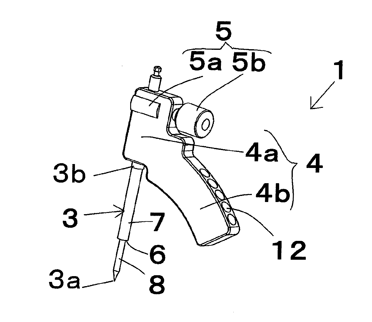
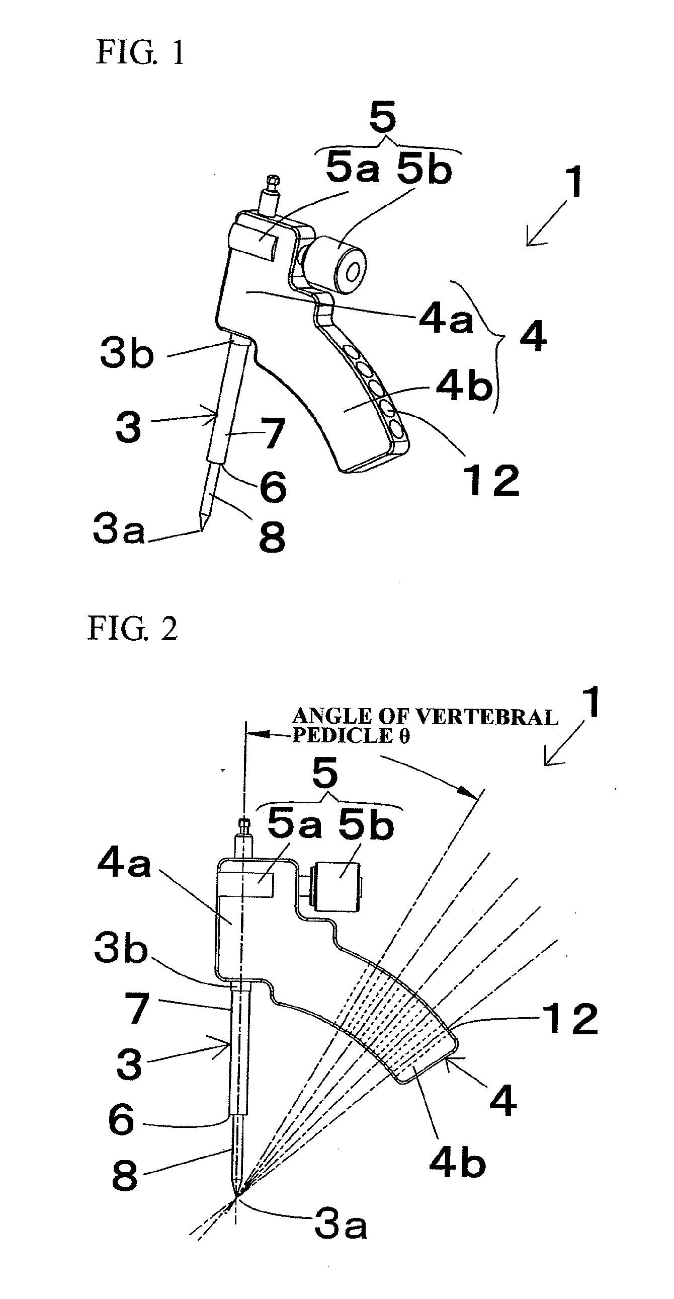
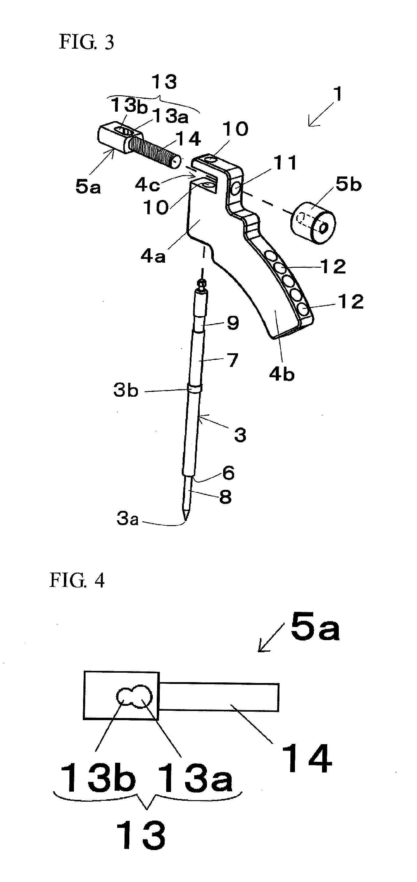
[0061]FIG. 1 is a perspective view of a boring instrument guiding device according to a first embodiment. FIG. 2 is a front view of the boring instrument guiding device according to the first embodiment. FIG. 3 is an exploded perspective view of the boring instrument guiding device according to the first embodiment. FIG. 4 is a plan view of a first fixing body. FIG. 5 is a view showing a use state of the boring instrument guiding device according to the first embodiment. FIG. 5(a) is a view showing a state in which a reference pin is inserted. FIG. 5(b) is a view showing a state in which a boring instrument is inserted. FIG. 6 is a view showing a state in which a pedicle screw is embedded. FIG. 7 is a view showing a variation of the reference pin.

[0062]A boring instrument guiding device 1 according to the present embodiment is a device for guiding a boring instrument 2 which forms a pilot hole for embedding a pedicle screw in a vertebral pedicle. A boring assembly is configured by c...

second embodiment

[0078]FIG. 8 is a perspective view of a boring assembly according to a second embodiment. FIG. 9 is a front view of the boring instrument guiding device according to the second embodiment. FIG. 10 is an exploded perspective view of the boring assembly according to the second embodiment. FIG. 11 is a view showing a use state of the boring instrument guiding device according to the second embodiment. FIG. 11(a) is a view showing a state in which the boring instrument guiding device is brought into contact with the vertebral arch. FIG. 11(b) is a view showing a state in which the reference pin is inserted. FIG. 11(c) is a view showing a state in which the boring instrument is inserted.

[0079]As shown in FIG. 8 to FIG. 11, in a boring instrument guiding device 1 according to the present embodiment, a caliper 16 is provided in addition to the configuration of the first embodiment. The other fundamental configurations of the present embodiment are the same as those of the above described f...


PUM


Abstract

A boring instrument guiding device which is used to guide a boring instrument that forms a pilot hole for embedding a pedicle screw in a vertebral pedicle includes a reference pin 3 which is used as a reference by being inserted into the vertebral arch from the rear to the front of a spine, and an arm 4 which extends sideward from the proximal end side of the reference pin 3, and is characterized in that a plurality of guide holes 12, each of which is opened toward the tip position 3a of the reference pin 3 to guide the boring instrument 2, are formed in the arm 4 in a radial pattern centered at the tip position 3a of the reference pin 3. It is possible to provide a boring instrument guiding device which is capable of more easily and precisely guiding the boring instrument.

Description

TECHNICAL FIELD[0001]The present invention relates to a boring instrument guiding device which, when a pilot hole for embedding a pedicle screw used for spinal fusion surgery as a spinal surgical operation is formed by a boring instrument, is used to precisely guide the insertion position and direction of the boring instrument, and relates to a boring assembly which forms the pilot hole.BACKGROUND ART[0002]FIG. 12 is an axial cross-sectional view of a spine. FIG. 13 is a view of the spine viewed from the front thereof. FIG. 14 is a view of the spine viewed from the side thereof. The spinal fusion surgery is an excellent operation method for correcting and fixing the spine. In such surgical operation of the spine, a method for embedding a pedicle screw in the spine is often used. The pedicle screw is embedded in such a manner that a pilot hole is formed beforehand by inserting a boring instrument, such as an awl and a tap, and that the pedicle screw is screwed into the pilot hole.[00...

Claims


Application Information

Patent Timeline
Patent Type & Authority Applications(United States)
IPC IPC(8): A61B17/16A61B17/56
CPCA61B17/1757A61B17/1671
Inventor SUDA, KOTA
Owner SUDA KOTA
Why Eureka
Try Eureka