Eureka AIR delivers breakthrough ideas for toughest innovation challenges, trusted by R&D personnel around the world.

Toploading internal combustion engine

Active Publication Date: 2010-12-30
BUCK SUPPLY
View PDF100 Cites 0 Cited by
  • Summary
  • Abstract
  • Description
  • Claims
  • Application Information

AI Technical Summary

Benefits of technology

[0011]It is an advantage of a method and system according to the present invention that an internal combustion engine may be assembled and disassembled from the top side of the engine, without the need for performing any significant operations below the crankshaft.
[0012]It is yet another advantage of a method and system according to the present invention that the engine may be installed in a more compact space, due to the absence of a need to access the lower portion of the engine in the event that work must be performed on the engine's power cylinders.

Problems solved by technology

This assembly technique causes unfortunate problems in the context of many usages of internal combustion engines.
For example, in marine usage, it is often very difficult to obtain access to the lower portion of an engine once it has been installed in a vessel.
Similarly, with many vehicle usages and even stationary usage of reciprocating engines, access to the lower portion of the crankcase is difficult, which makes it extremely difficult to work on the engine in place.
This, in turn, frequently necessitates expensive and time-consuming removal of the engine to allow it to be properly serviced.
Moreover, known internal combustion engines which have suffered spun main bearings or other bearing damage often require expensive and technically difficult resurfacing of the main bearing bores.
And, extensive damage in the area of the main bearing bores often necessitates the scrapping of motor blocks, at concomitantly high expense.

Method used


Image

  • Toploading internal combustion engine
  • Toploading internal combustion engine
  • Toploading internal combustion engine

Examples


Embodiment Construction

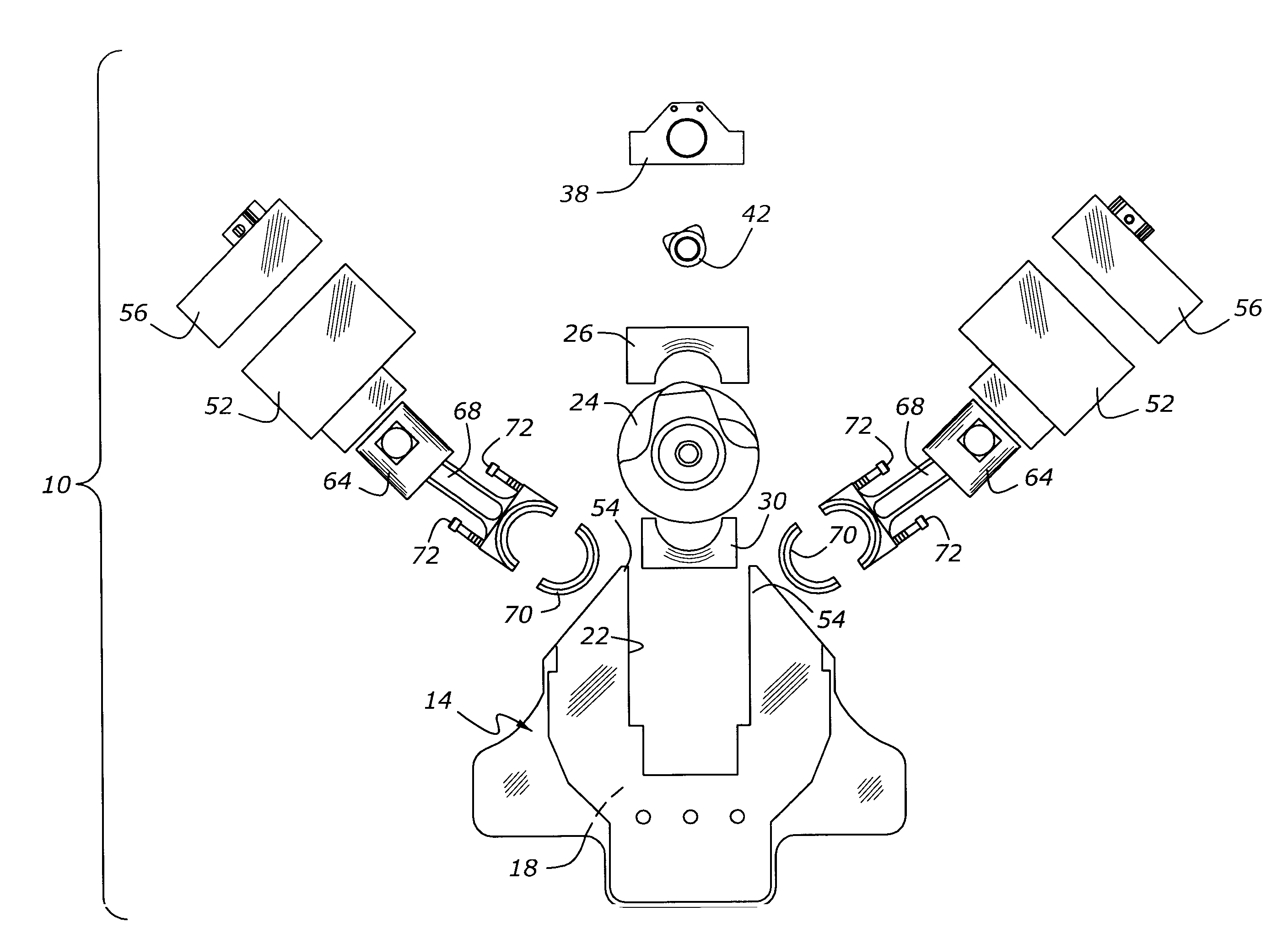
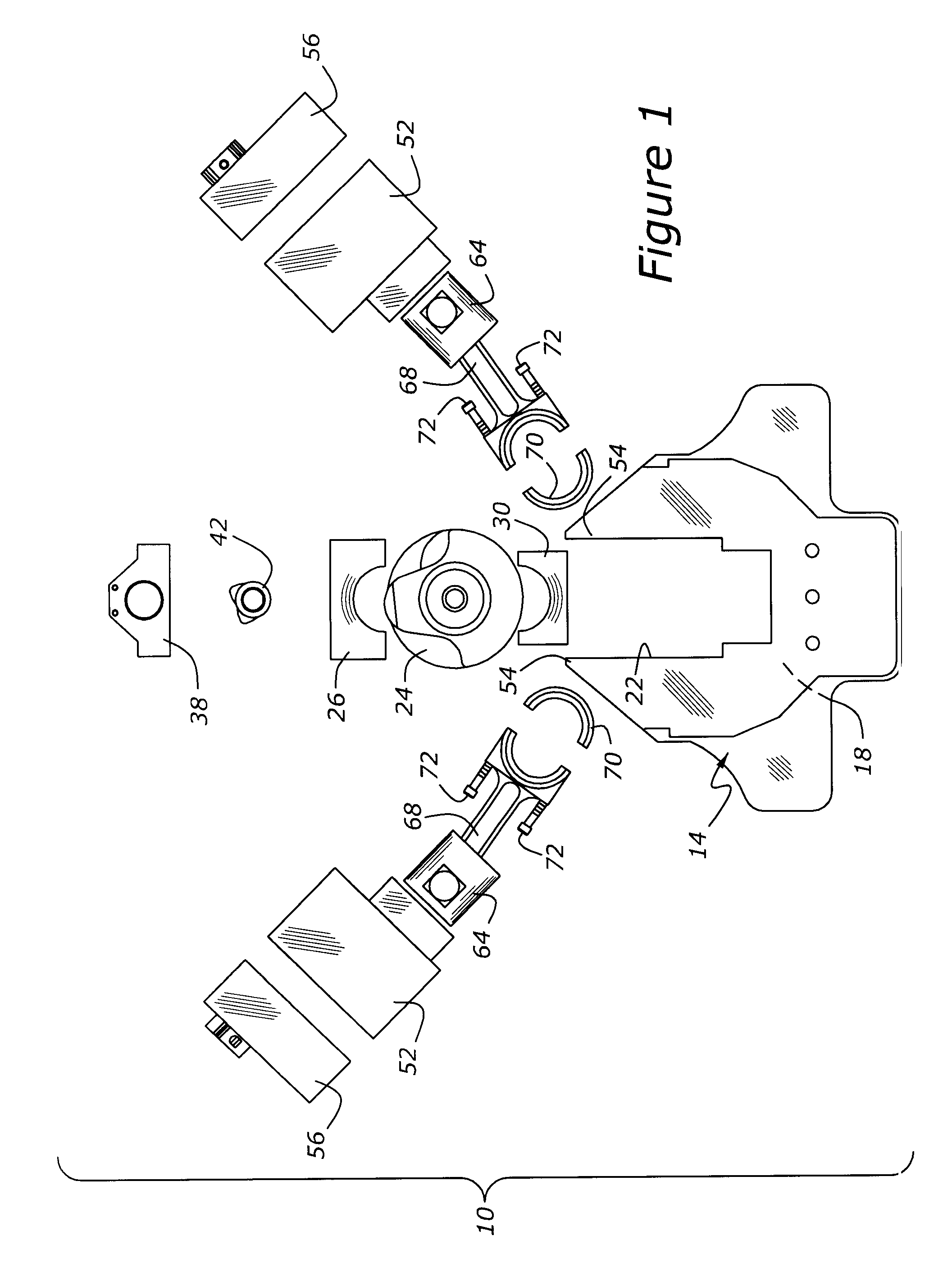
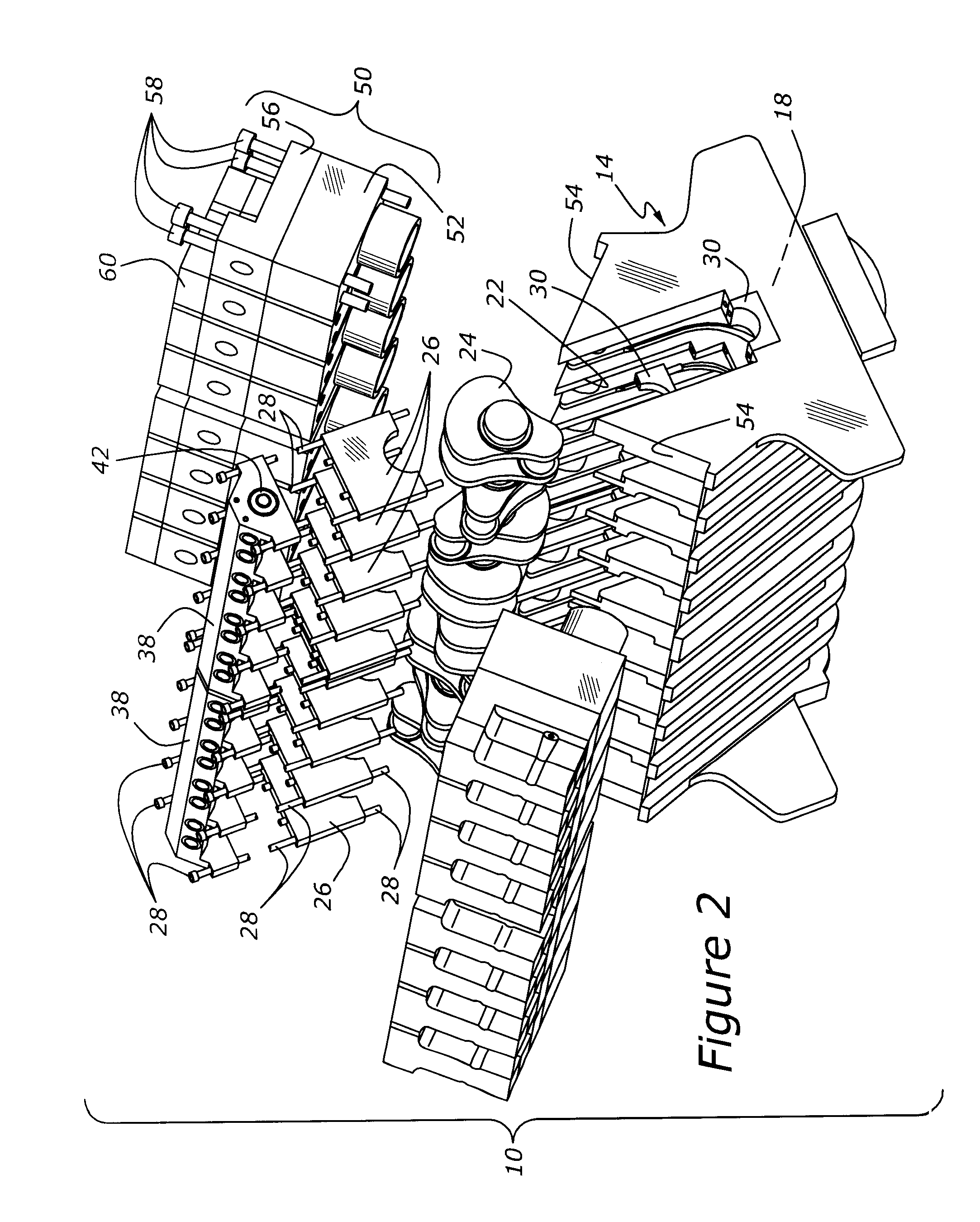
[0018]As shown in FIGS. 1 and 2, engine 10 is assembled into the upper portion of a carrier base, 14. Carrier base 14 has a lower portion configured as a crankcase, 18, and an upper portion having a number of upwardly directed assembly provisions, such as crankshaft bay 22 (FIGS. 2 and 4). During assembly of engine 10, crankshaft 24 is bedded into crankshaft bay 22 of carrier base 14 by first installing a number of lower bearing sections, 30, which are shown in FIGS. 1, 2 and 4. Bearing sections 30 may be secured by recessed cap screws (not shown) or alternatively, they may be configured to slide and lock into grooved portions of crankshaft bay 22. Once lower bearing sections 30 have been installed in crankshaft bay 22, along with an appropriate bearing insert (not shown), crankshaft 24 may be lowered into place and then secured with a number of main bearing caps 26. Main bearing caps 26 are secured with cap screws 28, which also serve to mount camshaft carrier 38 to the upper plane...


PUM


Abstract

An internal combustion engine includes a carrier base having a lower portion configured as a crankcase and an upper portion having a number of upwardly directed assembly provisions such as a crankshaft bay and at least one cylinder deck, with the crankshaft bay and cylinder deck being arranged so that the engine may be assembled from a position above the engine, without the necessity of attaching connecting rods or crankshaft main bearing bolts from underneath the engine.

Description

BACKGROUND OF THE INVENTION[0001]1. Field of the Invention[0002]The present invention relates to a multicylinder internal combustion engine which may be assembled from the top side of the engine without the need for accessing internal parts through a lower portion of the engine.[0003]2. Related Art[0004]Reciprocating internal combustion engines utilizing a crankshaft upon which a number of pistons and connecting rods are mounted typically require that assembly of the engine proceed with operations accessed from not only the top portion of the engine, but also the lower portion of the engine. Thus, when mounting a crankshaft within a conventional internal combustion engine, a cylinder block must be accessed from a lower portion of the engine, so as to allow the crankshaft to be placed into contact with the block, and secured with main bearing caps placed from underneath the engine. Then, pistons and connecting rods are inserted from the top of the engine; once again the fastenings fo...

Claims


Application Information

Patent Timeline
IPC IPC(8): B21K3/00F02F7/00
CPCF02F7/0031Y10T29/49231Y10T29/49234Y10T29/49229
Inventor BUCK, KENNETH M.
Owner BUCK SUPPLY
Why Eureka
Eureka Blog
Learn More