
Apparatus and method for joining solar receiver tubes

Active Publication Date: 2010-12-30
BUTTRESS DAVID
View PDF87 Cites 21 Cited by
  • Summary
  • Abstract
  • Description
  • Claims
  • Application Information

AI Technical Summary

Benefits of technology

[0011]The present invention overcomes the limitations and problems of the prior art by providing an apparatus and method for rapidly tubes, w

Problems solved by technology

Due their length, L, and glass components, solar receiver tubes tend to be fragile, and difficult to join, typically by welding, since the collars 114 protrude beyond the ends of the glass outer tube 110 by a relatively small distance from each end.

Method used


Image

  • Apparatus and method for joining solar receiver tubes
  • Apparatus and method for joining solar receiver tubes
  • Apparatus and method for joining solar receiver tubes

Examples


Embodiment Construction

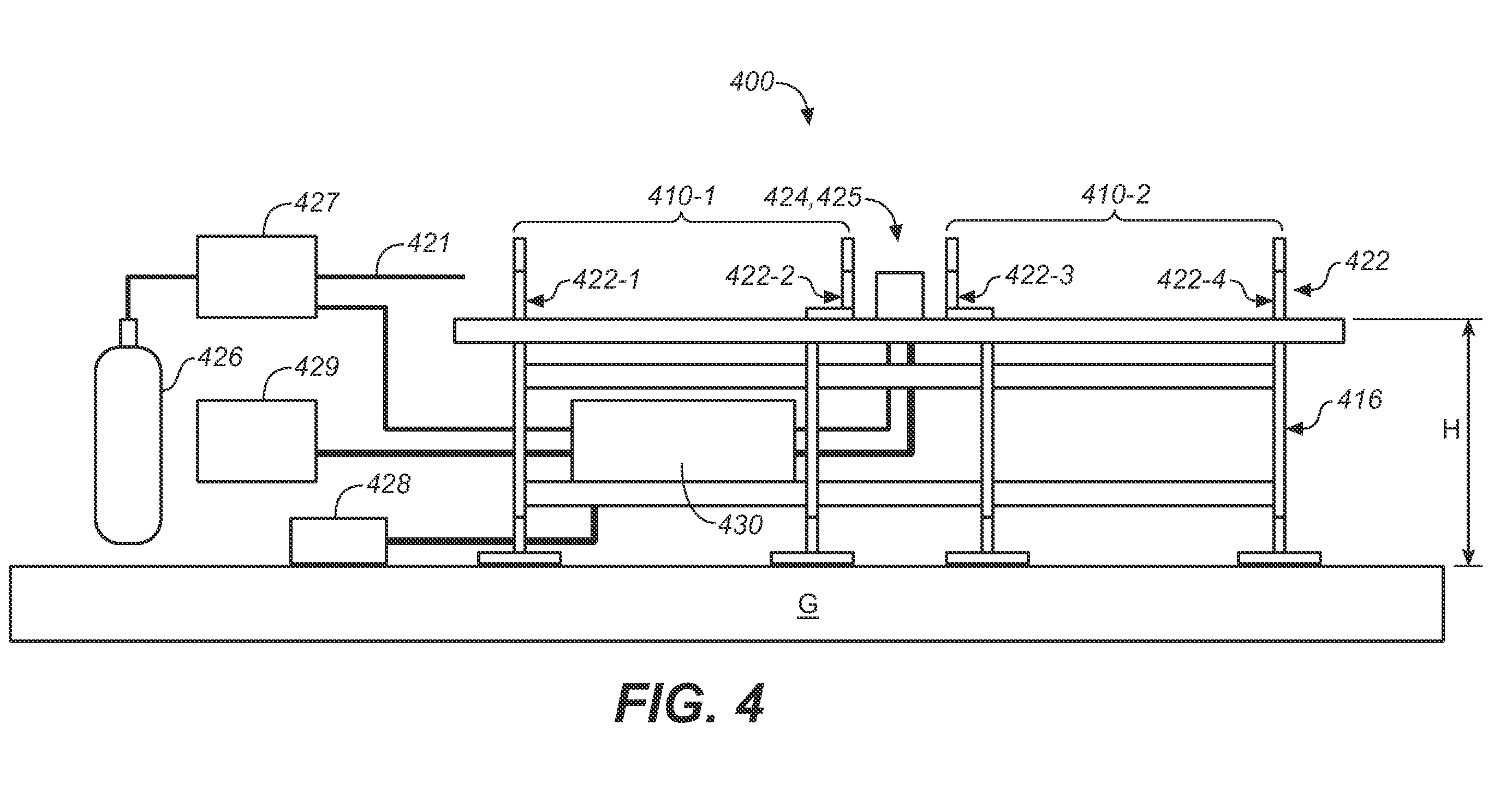
[0046]FIGS. 4-6 are schematics of one embodiment of a welding station 400, where FIG. 4 is a side view, FIG. 5 is a top view, and FIG. 6 is an end view. Welding station 400 includes a stand 416 for positioning the welding station on the ground G and to support tube stations 410, specifically a first tube station 410-1 and a second tube station 410-2, at a height H. The height H may be, for example and without limitation, from 3 feet (0.3 m) to 5 feet (1.5 m) above the ground.

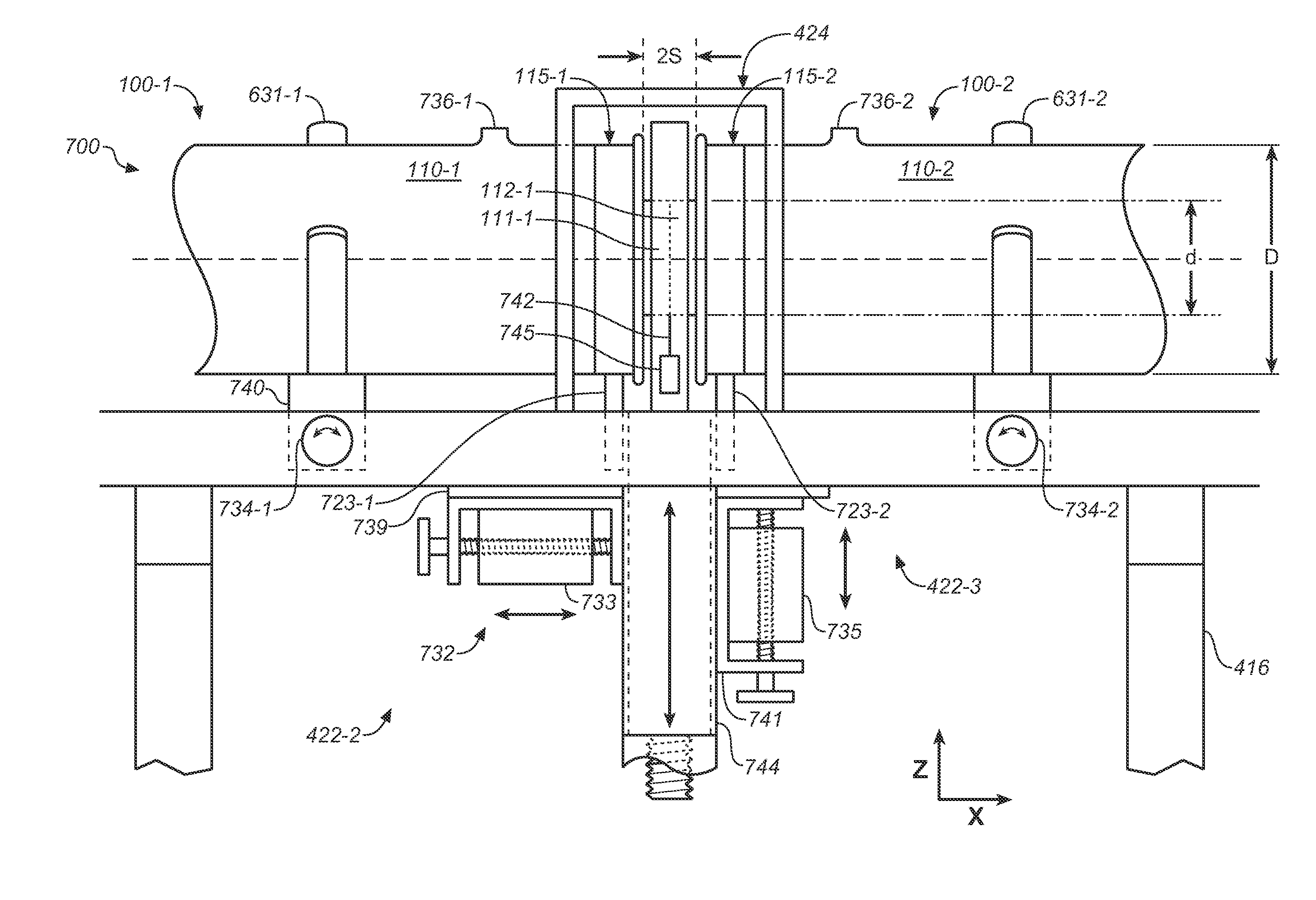
[0047]Tube stations 410-1 and 410-2 are each adapted to receive a solar receiver tube, such as two tubes 100, and both stations include two or more assemblies 422 for supporting the tube ends. Thus, for example and without limitation, four assemblies 422-1, 422-2, 422-3, and 422-4 are shown in FIG. 4, with station 410-1 associated with first assembly 422-1 and second assembly 422-2, and station 410-2 associated with third assembly 422-3, and fourth assembly 422-4. In general, assemblies 422 are positioned near t...


PUM


Abstract

A system for rapidly assembling solar receiving tubes and solar energy systems comprises a welding station is described. The welding station provides for rapidly assembling solar receiver tubes by welding together two or more solar receiving tubes and comprises means for receiving and restraining solar receiver tubes and a welding station comprising an orbital or a rotational weld head.

Description

CROSS-REFERENCE TO RELATED APPLICATIONS[0001]This Application claims the benefit of priority under 35 U.S.C. 119(e) to U.S. Provisional Application No. 61 / 220,120, filed Jun. 24, 2009, of U.S. Provisional Application No. 61 / 238,195, filed Aug. 30, 2009, both of which are incorporated by reference in their entirety.BACKGROUND OF THE INVENTION[0002]1. Field of the Invention[0003]The present invention generally relates to apparatus and methods for assembling pipes, and more particularly to methods and systems for joining tubes for solar receivers.[0004]2. Description of Related Art[0005]Solar thermal power plants may be used to obtain electric power from the sun. In such plants, the solar flux impinges on tubes through which a heat exchange medium flows. In some solar thermal power plants, tubes are situated in a solar collector, such as along the axis of a parabolic trough. The heated heat exchange medium from the tubes may be used in a thermodynamic cycle to generate electric power.[...

Claims


Application Information

Patent Timeline
IPC IPC(8): B23P15/26B23K31/02F24S10/70
CPCB23K9/0286B23K37/053Y10T29/49393Y10T29/49355B23K37/0533F24S10/45F24S80/30F24S2025/6011Y02E10/44Y10T29/49357B23K9/16
Inventor BUTTRESS, DAVID
Owner BUTTRESS DAVID
Features
  • Generate Ideas
  • Intellectual Property
  • Life Sciences
  • Materials
  • Tech Scout
  • Unparalleled Data Quality
  • Higher Quality Content
  • 60% Fewer Hallucinations
Learn More