System for mitigating a fuel system transient

a technology of a fuel system and a transient, applied in the field of fuel systems, can solve the problems of increasing the likelihood of an unacceptably high speed of the turbomachine rotor, increasing the likelihood of a transient event, and increasing the rotor speed of the turbomachine, so as to achieve the effect of mitigating the effect of the fuel system transien

Inactive Publication Date: 2010-12-30
GENERAL ELECTRIC CO
View PDF10 Cites 4 Cited by
  • Summary
  • Abstract
  • Description
  • Claims
  • Application Information

AI Technical Summary

Benefits of technology

[0009]In accordance with an embodiment of the present invention, a system for mitigating a transient experienced by a fuel system, the system comprising: a primary fuel circuit configured for delivering a fuel to a combustion process, wherein the primary fuel circuit comprises: a valve configured for controlling a flow of the fuel; and a primary manifold configured for apportioning the fuel to components of the combustion process; wherein the primary manifold is located downstream of the valve; and a pressure control cell (PCC) configured for relieving the pressure within the primary manifold during a fuel system transient; wherein the PCC removes a potion of the fuel within the primary manifold during the fuel system transient and mitigates the effect of the fuel system transient on the fuel system.
[0010]In accordance with another embodiment of the present invention, a system for mitigating a transient experienced by a turbomachine, the system comprising: a turbomachine comprising a combustion can and a fuel system adapted for delivering a fuel to the combustion can; wherein the fuel system comprises: a first fuel circuit configured for supplying the fuel to the combustion can, wherein the first fuel circuit comprises: a device configured for controlling a flow of the fuel; and a first manifold configured for apportioning the fuel to components of the combustion can; wherein the first manifold is located downstream of the device: and a pressure control cell (PCC) configured for reducing the pressure within the first manifold during a fuel system transient; wherein the PCC removes a potion of the fuel within the primary manifold during the fuel system transient and mitigates the effect of the fuel system transient on the fuel system.

Problems solved by technology

Transient requirements for turbomachines, including continued operation after a transient event, are becoming increasingly demanding.
This may increase the likelihood of an unacceptably high speed of the turbomachine rotor.
The high rotor speed may result from the fuel that remains downstream of the valve after the fuel flow is rapidly reduced.
This fuel is consumed by the combustion process and may cause the rotor speed increase.
After the transient event, this remaining fuel is combusted, may drive the turbomachine towards an overspeed condition, and may also increase airflow to the combustion can, which may cause a lean blowout.
There are a few disadvantages of using known systems and control philosophies during a transient event.
Furthermore, some known systems may allow too much air to enter the turbomachine during the transient, increasing the lean blowout risk.

Method used


Image

  • System for mitigating a fuel system transient
  • System for mitigating a fuel system transient
  • System for mitigating a fuel system transient

Examples


Embodiment Construction

[0016]Certain terminology is used herein for convenience only and is not to be taken as a limitation on the invention. For example, words such as “upper,”“lower”, “left”, “front”, “right”, “horizontal”, “vertical”, “upstream”, “downstream”, “fore”, “aft”, “top”, “bottom”, “upper”, and “bottom” merely describe the configuration shown in the FIGS. Indeed, the components may be oriented in any direction and the terminology, therefore, should be understood as encompassing such variations unless specified otherwise.

[0017]As used herein, an element or step recited in the singular and preceded with “a” or “an” should be understood as not excluding plural elements or steps, unless such exclusion is explicitly recited. Furthermore, references to “an embodiment” of the present invention are not intended to exclude additional embodiments incorporating the recited features.

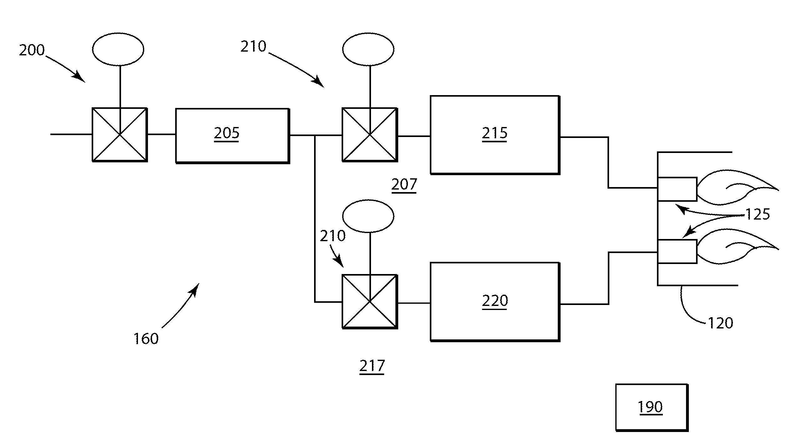
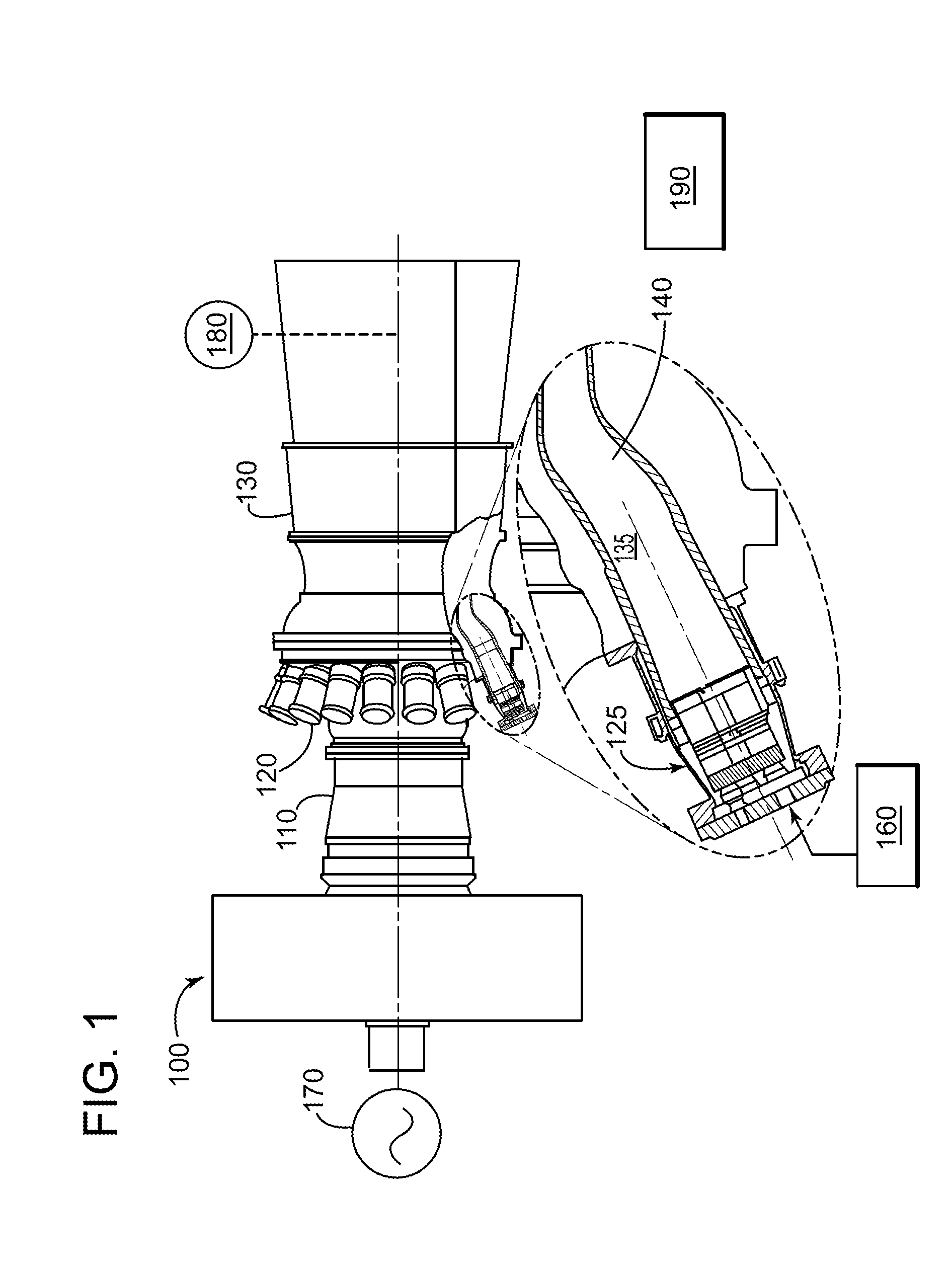
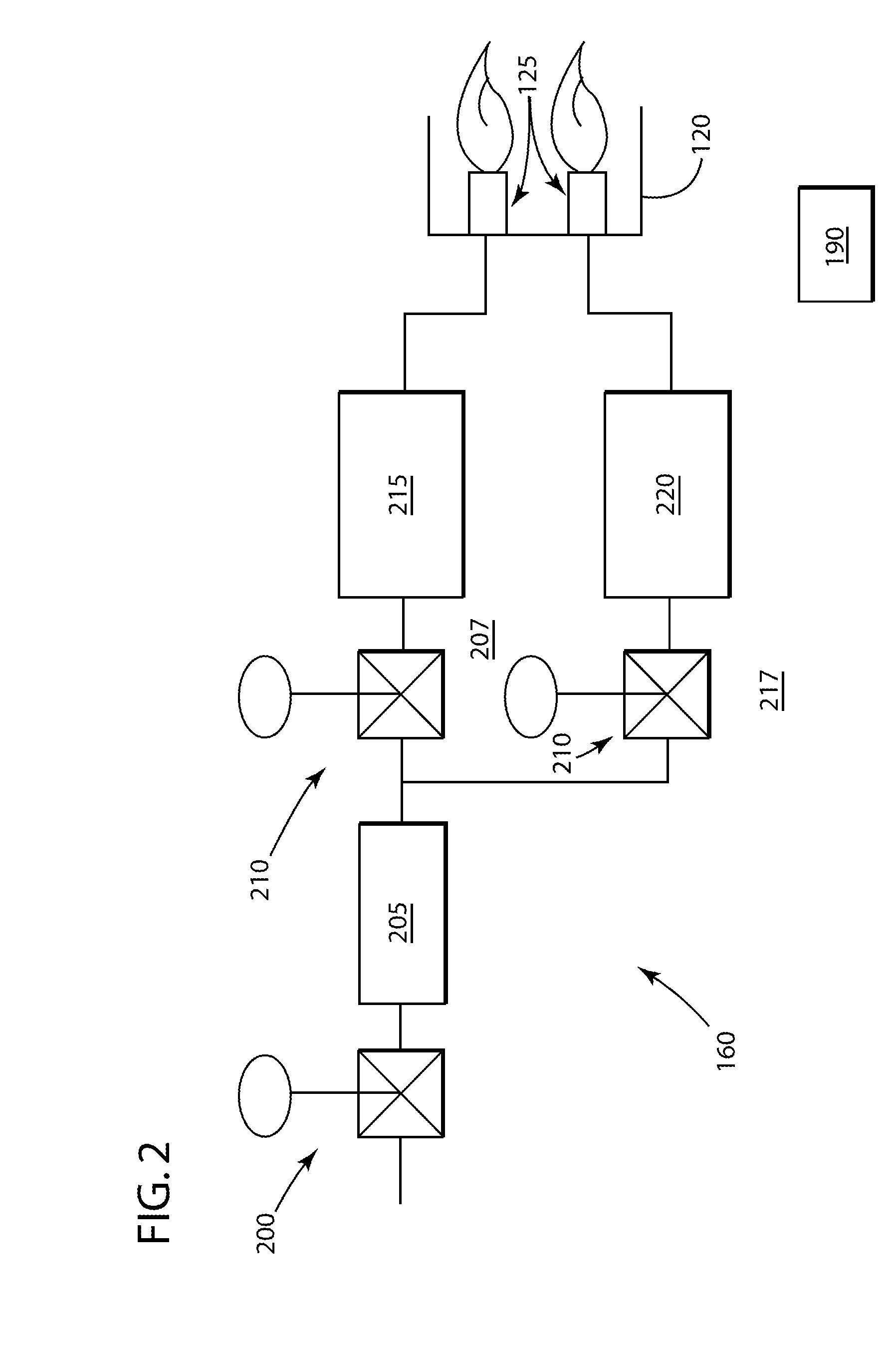
[0018]The present invention takes the form of a system that may reduce the effect of a transient of a fuel system. The foll...


PUM


Abstract

The present invention takes the form of a system that may reduce the effect of a transient of a fuel system. Essentially, an embodiment of the present invention incorporates a pressure control cell (PCC) with the fuel system. The PCC may be considered an additional volume that removes some of the fuel remaining in the fuel system during a transient event. During a transient event, when a rapid reduction of fuel is required for a fuel circuit, fuel may be allowed to exit a manifold of the fuel system and enter the PCC. This fuel may now be stored within the PCC and may no longer be available to the combustion can. A benefit of the present invention may be a reduced possibility of an undesired increase in rotor speed, and a lean blowout event.

Description

[0001]This application is related to commonly-assigned U.S. patent application Ser. No. ______ [GE Docket 239283], filed ______.BACKGROUND OF THE INVENTION[0002]The present application relates generally to a fuel system associated with a combustion process; and more particularly to, a system for mitigating an effect of a transient on the fuel system.[0003]Fuel systems are associated with a wide-variety of combustion processes of a machine. The fuel system generally serves to transport a fuel, such as, but not limiting of, a natural gas, to the combustion process. The fuel system generally includes a manifold and a valve that collectively control the fuel flow to the combustion process. The fuel system may also control the pressure of the fuel supplied to the valve. The valve may function as the primary control of gas flow to combustion process.[0004]A turbomachine is a non-limiting example of a machine with a combustion process. Some turbomachines, such as, but not limiting of, a ga...

Claims


Application Information

Patent Timeline
Patent Type & Authority Applications(United States)
IPC IPC(8): F02C7/22
CPCF02C9/28
Inventor SNIDER, DAVID A.
Owner GENERAL ELECTRIC CO
Why Eureka
Try Eureka