Vapor chamber with separator

a technology of separator and vapor chamber, which is applied in the field of vapor chamber, can solve the problems that the prior vapor chamber structure still has some drawbacks in practical use, and achieve the effect of significantly boosting cooling performan

Inactive Publication Date: 2010-12-30
CELSIA TECH TAIWAN INC
View PDF24 Cites 20 Cited by
  • Summary
  • Abstract
  • Description
  • Claims
  • Application Information

AI Technical Summary

Benefits of technology

[0011]Compared with prior arts, the invention has following merits. Since the separator separates the working fluid in vapor phase from the working fluid in liquid phase, the working fluid of each phase has its own passage to avoid interfering to each other, reaching the function of

Problems solved by technology

However, the prior vapor chamber structure still has some drawbacks in terms of practical usage.
Since the phase change between vapor and liquid occurs in a same accommodating space, it will substantially happe

Method used


Image

  • Vapor chamber with separator
  • Vapor chamber with separator
  • Vapor chamber with separator

Examples


Embodiment Construction

[0017]In cooperation with attached drawings, the technical contents and detailed description of the present invention are described thereinafter according to a preferable embodiment, not used to limit its executing scope. Any equivalent variation and modification made according to appended claims is all covered by the claims claimed by the present invention.

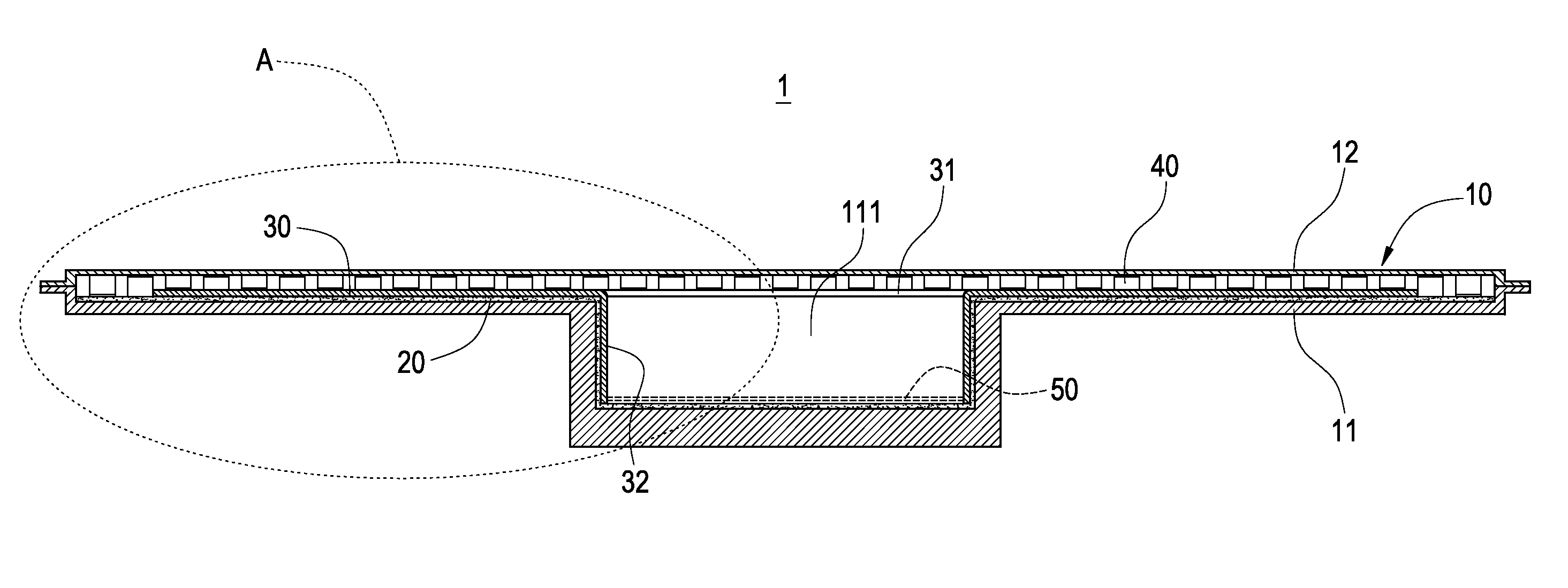
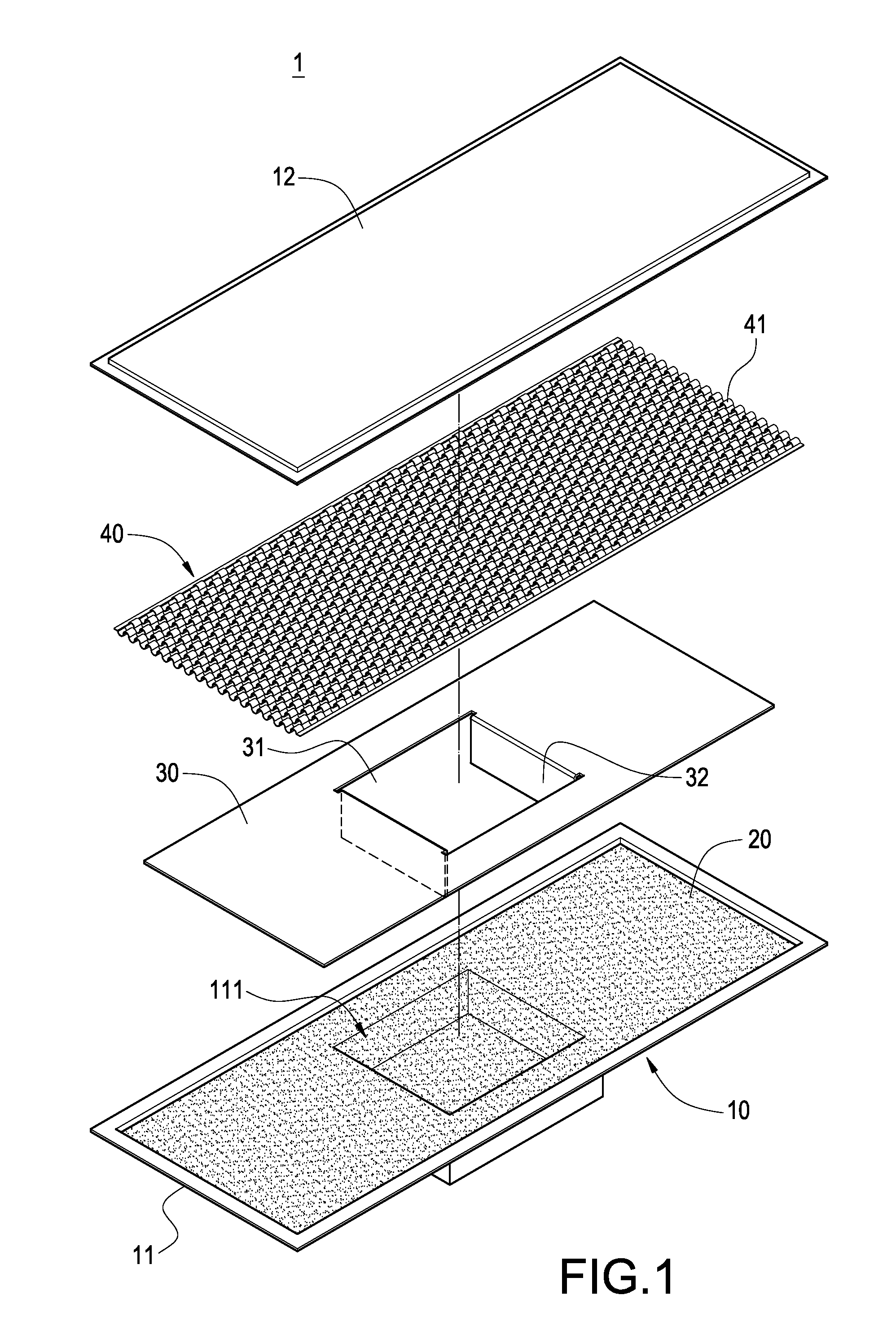
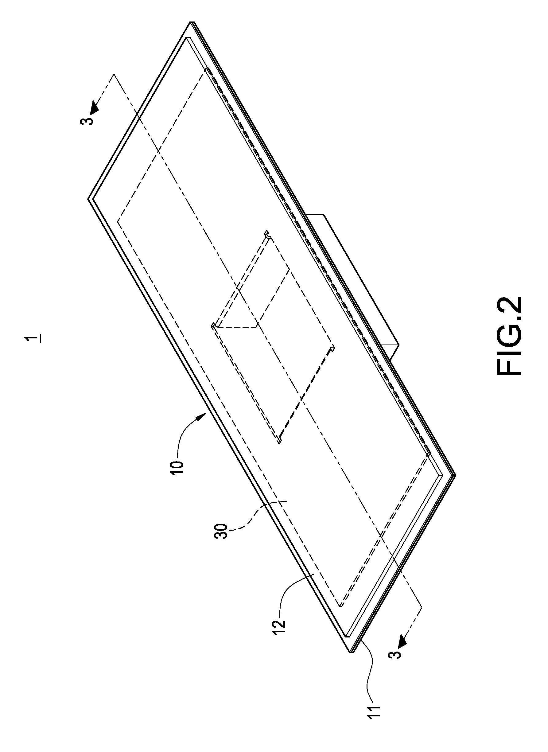
[0018]Please refer to FIG. 1 and FIG. 2, respectively showing a perspective explosive view and a perspective outer view of the invention. The invention is to provide a vapor chamber 1 with separator 30, including a shell 10, a capillary tissue 20, a separator 30, a supporting structure 40 and a working fluid 50 (referring to FIG. 4).

[0019]The shell 10 includes a lower shell plate 11 and an upper shell plate 12 sealing the lower shell plate 11. Partial section of the lower shell plate 11 is projected downwardly to form an accommodating room 111 therein. In this embodiment, the accommodating room 111 is shown as a rectangular confi...


PUM


Abstract

A vapor chamber with separator includes shell, capillary tissue, separator, supporting structure and working fluid. The shell includes inter-sealed lower and upper shell plates. Partial section of the lower shell plate projects downwardly and forms accommodating room therein. The capillary tissue is arranged by distributing over inner wall of the lower shell plate. The separator overlapped the capillary tissue is arranged penetrating trough corresponding to the accommodating room. Liquid passage is formed between the lower shell plate and the separator. The supporting structure is accommodated in the shell with upper and lower sides respectively inter-abutted against the upper shell plate and the separator. Vapor passage formed between the upper shell plate and the separator is communicated to the liquid passage. The working fluid is filled into the shell. Since the vapor and liquid working fluids are separated by the separator to avoid interference, the cooling performance is thus boosted.

Description

BACKGROUND OF THE INVENTION[0001]1. Field of the Invention[0002]The present invention in general relates to a vapor chamber, in particular, to a vapor chamber with separator.[0003]2. Description of Prior Art[0004]The quicker computing speed of a computer is, relatively the more waste heat of computing element (for example, CPU) in computer generates. How to remove the waste heat from the interior of computer chassis in time to make computing element operated under normal temperature has become an issue intended to be addressed urgently by each manufacturer.[0005]In order to enhance the cooling performance of computer chassis, the use of vapor chamber can boost the cooling efficiency significantly. As a general rule, a prior vapor chamber includes an upper shell plate, a lower shell plate, a capillary tissue, a supporting structure and a working fluid. The upper shell plate and the lower shell plate are inter-sealed to each other, between which an accommodating space is formed. The c...

Claims


Application Information

Patent Timeline
IPC IPC(8): F28D15/00
CPCF28D15/0233F28D15/04F28D15/046H01L23/427H01L2924/0002H01L2924/00
Inventor MEYER IV, GEORGE ANTHONY.SUN, CHIEN-HUNGCHEN, CHIEH-PINGCHIN, TE-HSUAN
Owner CELSIA TECH TAIWAN INC
Why Eureka
Try Eureka