
Wind energy installation having converter control

a technology of wind energy installation and converter control, which is applied in the direction of dynamo-electric converter control, electric generator control, machines/engines, etc., can solve the problem of no longer being able to achieve the additionally required current, and achieve the effect of preventing excessive load on the inverter and better us

Active Publication Date: 2010-12-30
SIEMENS GAMESA RENEWABLE ENERGY SERVICE GMBH
View PDF7 Cites 34 Cited by
  • Summary
  • Abstract
  • Description
  • Claims
  • Application Information

AI Technical Summary

Benefits of technology

The present invention provides a method and apparatus for controlling a converter of a wind energy installation, which can improve the performance of the wind energy installation by optimizing the total current output and reducing the load on the individual inverters. The method involves detecting changes in the electrical voltage, real currents, and reactive currents, and adjusting the regulation of the inverters accordingly to match one another and optimize the current output. This approach also allows the inverters to support one another when the operating conditions of the wind energy installation change unpredictably, reducing the risk of damage or disconnection. The invention also provides a maximum predeterminable nominal value for the reactive currents that can be determined based on the emitted real currents and a predeterminable control margin for the real currents.

Problems solved by technology

In the case of the doubly-fed asynchronous generators which are preferably used for relatively high power wind energy installations, one problem that arises is that the grid-feeding inverters are designed for only about ⅓ of the electrical power and it is now no longer possible to achieve the additionally required currents in order to ensure grid-supporting characteristics.
This solution has the disadvantage that it can be used only when the generator rotor is not emitting any power.

Method used


Image

  • Wind energy installation having converter control
  • Wind energy installation having converter control
  • Wind energy installation having converter control

Examples


Embodiment Construction

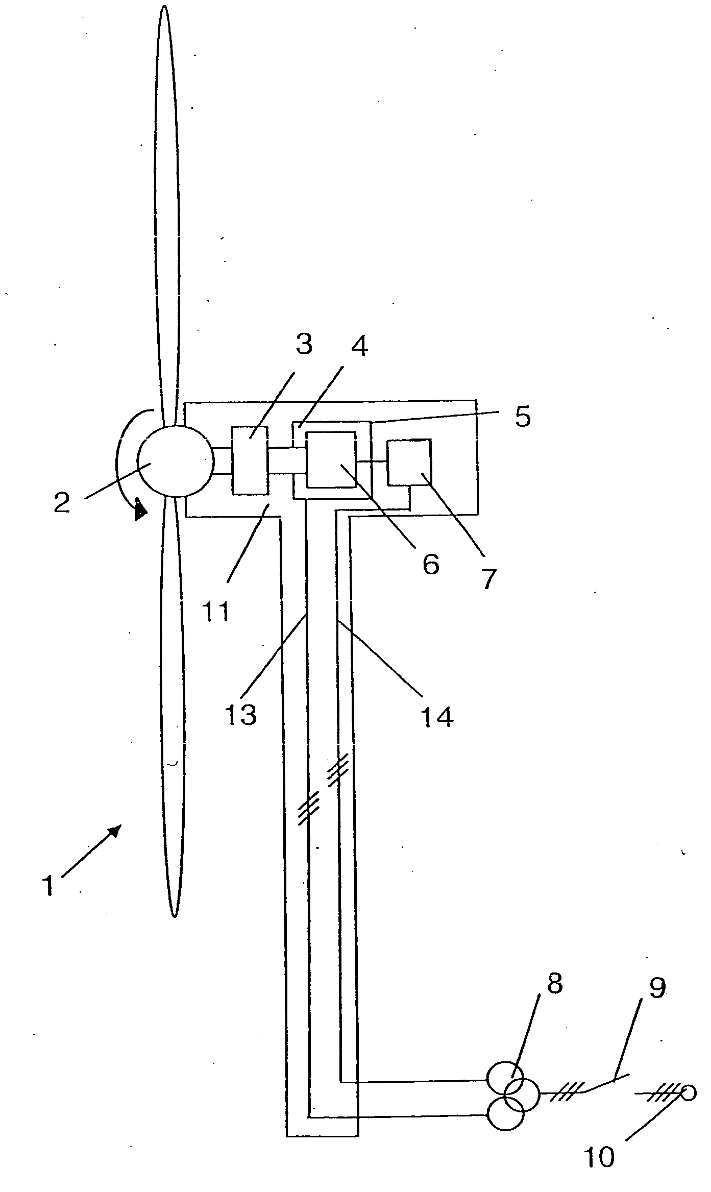
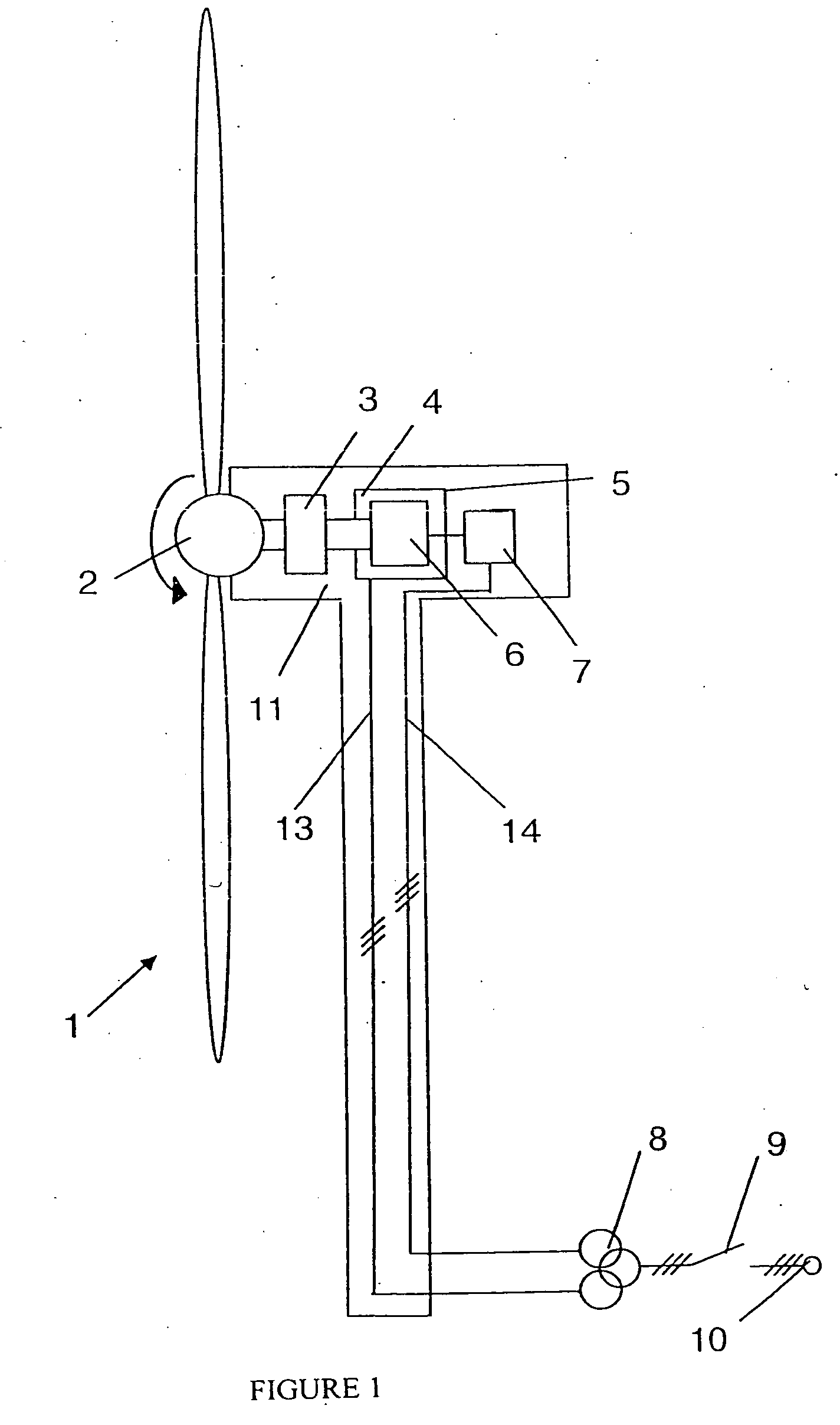
[0034]The design of the wind energy installation will be explained briefly with reference to FIG. 1. The wind rotor 2 of the wind energy installation 1 is caused to rotate by the wind. In this case, the wind rotor 2 is mechanically connected to the generator 4 via a gearbox 3, and causes the rotor 6 of the generator 4 to rotate. The stator 5 of the generator is connected to the electrical grid 10 via power cables 13 in the tower, a transformer 8 and a switch disconnector 9. The rotor 6 of the generator 4 is connected to a converter 7 which is in turn connected to the electrical grid 10, likewise via power cables 14 in the tower, a transformer 8 and a switch disconnector 9.

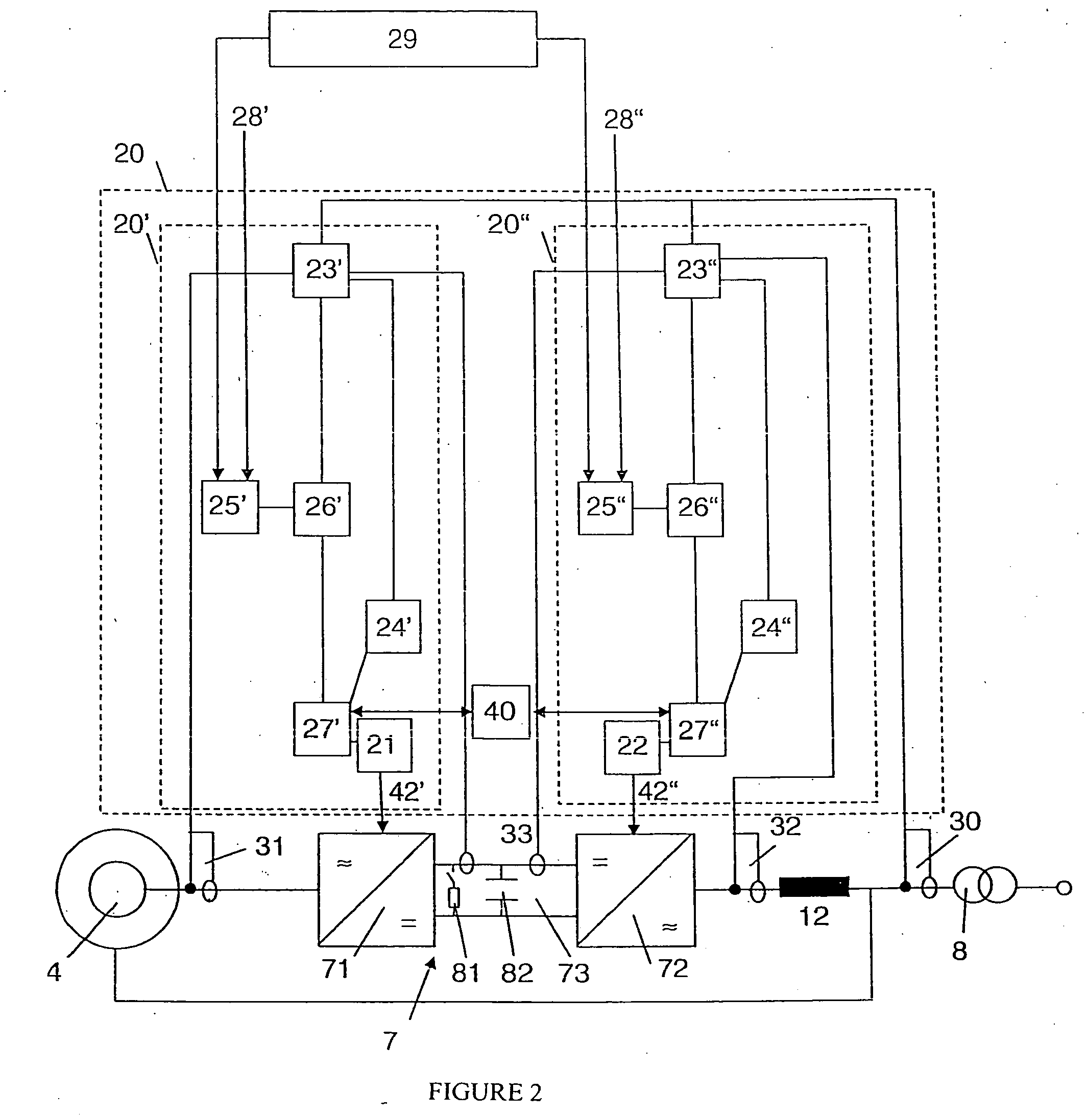
[0035]In this case, the transformer 8 is a transformer with three windings, that is to say in each case with separate windings for the power strand of the grid-side inverter 72 and the generator-side inverter 71. Embodiments with two or a different number of windings are likewise feasible. When the generator 4, whi...


PUM


Abstract

A method for controlling a converter of a wind energy installation. The converter is connected to a rotor of a doubly-fed asynchronous generator for feeding electrical power into an electrical grid and comprises a generator-side inverter, a grid-side inverter, and at least one converter regulator for regulating and / or controlling currents emitted from at least one of the inverters to at least one of the generator and the electrical grid. The method includes detecting a change in electrical voltage present in at least one of emitted real currents and emitted reactive currents at one of the inverters, determining whether the detected change corresponds to a predetermined change, and changing nominal values of at least one of real currents to be emitted and reactive currents to be emitted from the other inverter if the detected change corresponds to the predetermined change.

Description

REFERENCE TO RELATED APPLICATIONS[0001]This application is a national stage application under 35 USC 371 of International Application No. PCT / EP2009 / 001140, filed Feb. 18, 2009, which claims the priority of German Patent Application Nos. 10 2008 010 260.1, filed Feb. 20, 2008, and 10 2008 034 532.6, filed Jul. 24, 2008, the contents of which prior applications are incorporated herein by reference.FIELD OF THE INVENTION[0002]The invention relates to a converter of a wind energy installation, which converter is connected to the rotor of a doubly-fed asynchronous generator for feeding electrical power into an electrical grid, with the converter having a generator-side inverter and a grid-side inverter, and to a method for controlling the converter.BACKGROUND OF THE INVENTION[0003]Frequency converters are being increasingly used for wind energy installations. Modern wind energy installations normally have a variable rotation speed, as a result of which the generator produces alternating...

Claims


Application Information

Patent Timeline
Patent Type & Authority Applications(United States)
IPC IPC(8): H02P9/04H02P9/48H02P9/10
CPCF03D9/002H02J3/18H02J3/1892H02M5/4585H02P9/007H02P2101/15Y02E10/725Y02E10/763Y02E40/30H02J3/386H02P2207/01F03D9/25F03D9/255H02J2300/28H02J3/381Y02E10/76Y02E10/72H02J3/48H02J3/50
Inventor FORTMANN, JENS
Owner SIEMENS GAMESA RENEWABLE ENERGY SERVICE GMBH
Learn More