
System and method for detecting lightning

a detection system and lightning technology, applied in the field of lightning detection systems, can solve the problems of wind turbines, in particular, being subject to a high risk of lightning strikes, and the system cannot detect the number of lightning sequences striking a wind turbine, and the affected blade cannot be automatically identified via use of lightning detection systems

Active Publication Date: 2010-12-30
GENERAL ELECTRIC CO
View PDF22 Cites 19 Cited by
  • Summary
  • Abstract
  • Description
  • Claims
  • Application Information

AI Technical Summary

Benefits of technology

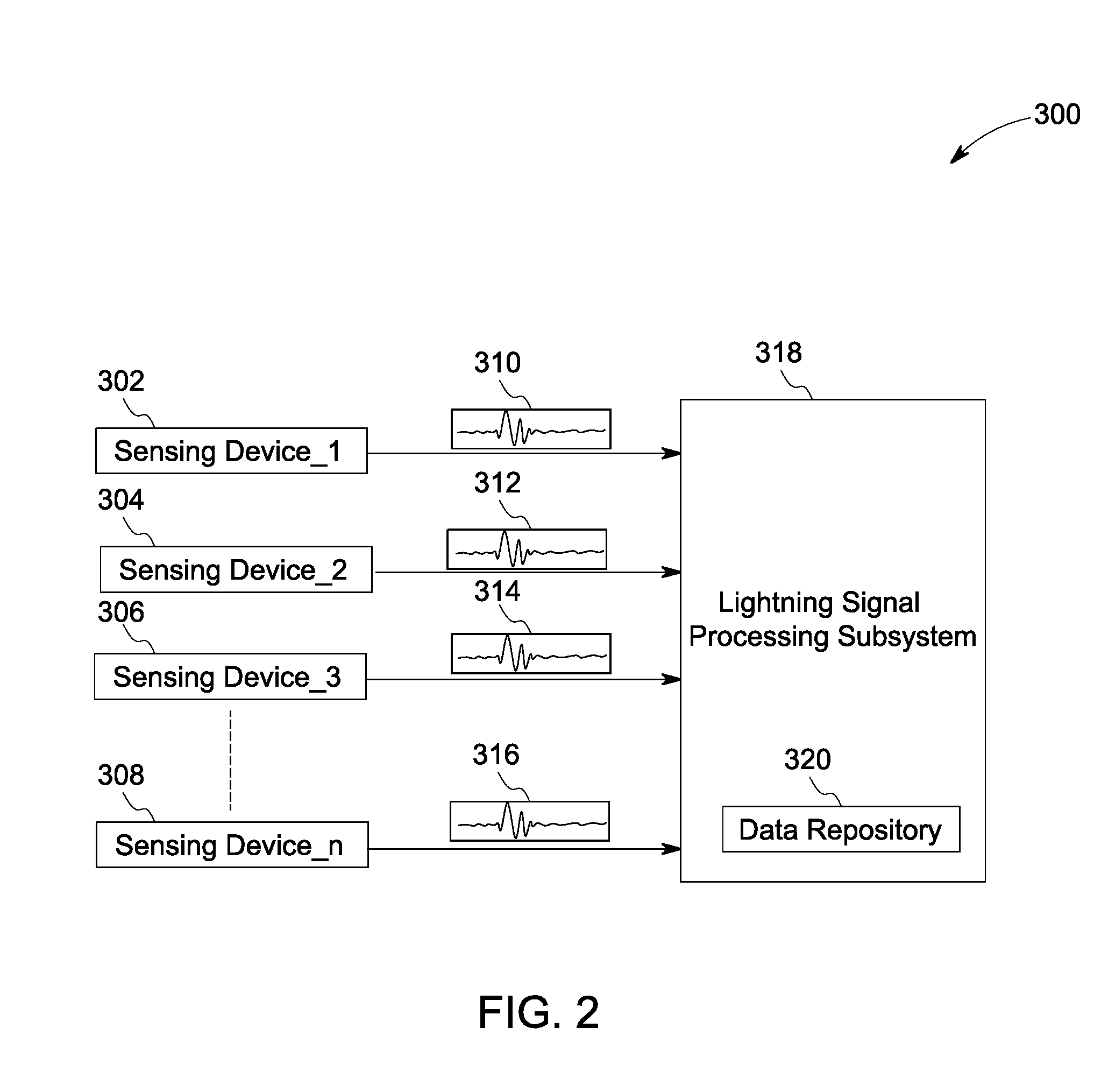
[0006]Briefly in accordance with one aspect of the technique, a lightning detection system is presented. The lightning detection system includes a plurality of sensing devices configured to generate sensor signals representative of one or more working state parameters of an object. The lightning detection system further includes a lightning signal processing subsystem configured to combine the sensor signals representative of the one or more working state parameters received from the plurality of sensing devices to generate a composite signal, extract noise signals from the composite signal, and compare the extracted noise signals with one or more lightning signal profiles to determine the existence of lightning noise signals in the extracted noise signals.
[0007]In accordance with another aspect of the present technique, a lightning detection system is presented. The lightning detection system includes a plurality of sensing devices configured to generate sensor signals representative of one or more working state parameters of an object. The lightning detection system further includes a sensing subsystem including one or more sensing modules and configured to extract noise signals from the sensor signals representative of the one or more working state parameters of the object received from the plurality of sensing devices and compare the extracted noise signals with one or more lightning signal profiles to determine existence of lightning noise signals in the extracted noise signals. The lightning detection system also includes a lightning signal processing subsystem in operative communication with the sensing subsystem and configured to combine the extracted noise signals received from the sensing subsystem to generate a composite noise signal based on determination of lightning noise signals in at least one of the extracted noise signals, wherein the lightning noise signals are induced in the sensor signals in response to a lightning strike on the object.
[0008]In accordance with still another embodiment of the present technique, a lightning detection method is presented. The method includes combining one or more sensor signals representative of one or more working state parameters to generate a composite signal, wherein the on

Problems solved by technology

Wind turbines, in particular, are generally subjected to a high risk of lightning strikes as they are preferentially placed at high and windy locations in order to achieve high productivity.
However, the system is unable to detect the number of lightning sequences striking a wind turbine between periods of two magnetic card readings.
Unfortunately, in most cases, the system has to be reset by an acknowledgement signal.
Moreover, an affected blade cannot be automatically identified via use of these lightning detection systems.
Furthermore, conventional lightning detection systems, including the abovementioned two categories of lightning detection systems typically require installation of specialized sensors such as small antennas, magnetic cards, and the like for detection of a lightning strike.
The installation of supplementary sensors thus results in additional cost for detection of the lightning strike.
However, these conventional systems fail to register lightning event parameters or localization of impact.

Method used


Image

  • System and method for detecting lightning
  • System and method for detecting lightning
  • System and method for detecting lightning

Examples


Embodiment Construction

[0018]As will be appreciated, a wind turbine is susceptible to lightning strikes. The lightning strike may damage the wind turbine, and more particularly the wind turbine blades thereby resulting in downtime and repairs. It is therefore desirable to develop a lightning detection system to detect a lightning strike in a timely manner, and hence reduce repairs and downtime of the wind turbine.

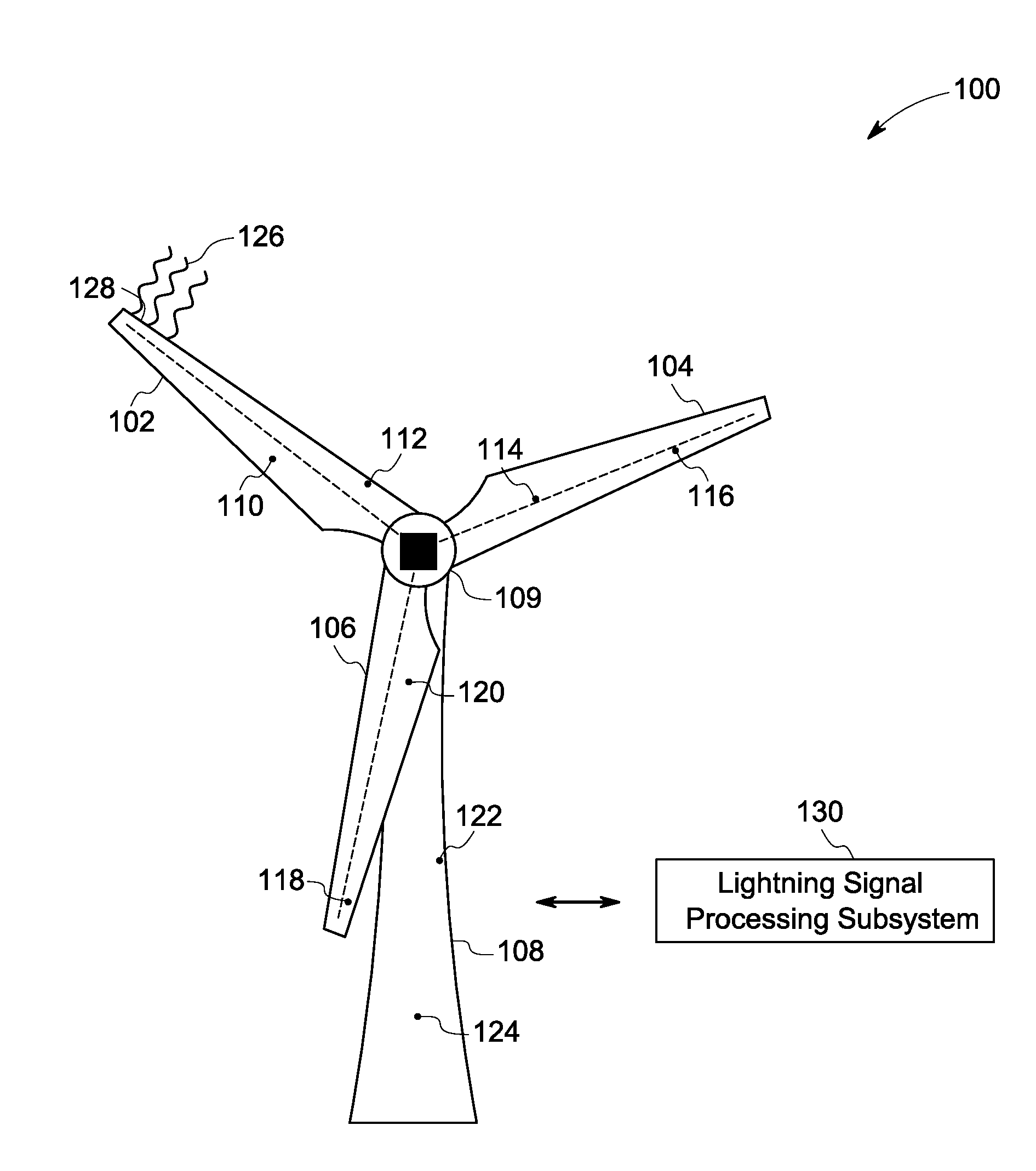
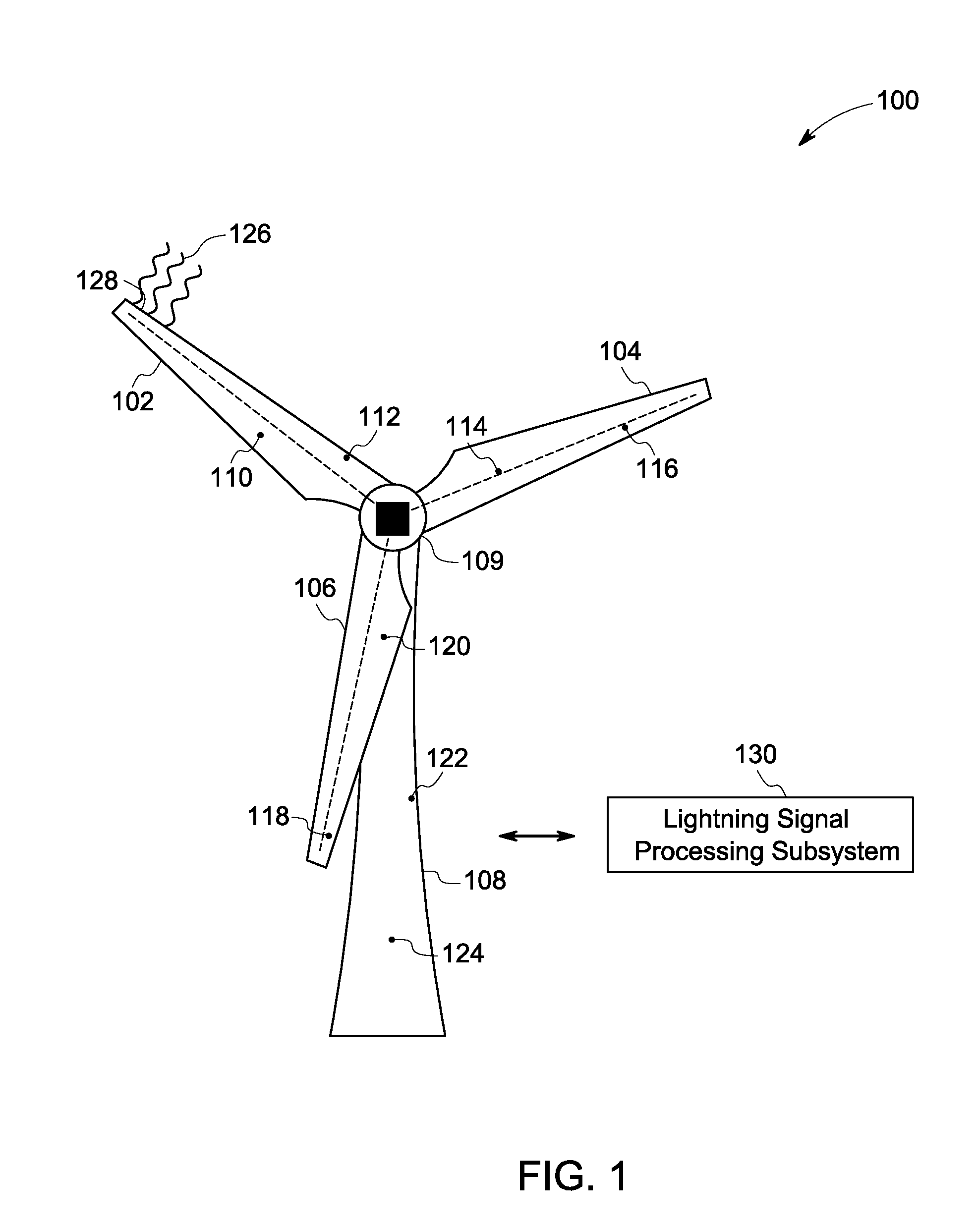
[0019]FIG. 1 is a diagrammatical view of a wind turbine 100 including an exemplary lightning detection system, in accordance with aspects of the present technique. As used herein, the term “wind turbine” may be used to refer to a rotating machine that converts kinetic energy of wind to mechanical energy. The mechanical energy may then be converted to electrical energy.

[0020]In an exemplary embodiment, the wind turbine 100 includes a tower 108, blades 102, 104 and 106, a nacelle 109 and a hub (not shown in FIG. 1). In a presently contemplated configuration, the blade 102 includes sensing devices 1...


PUM


Abstract

A lightning detection system is presented. The lightning detection system includes a plurality of sensing devices configured to generate sensor signals representative of one or more working state parameters of an object. The lightning detection system further includes a lightning signal processing subsystem configured to combine the sensor signals representative of the one or more working state parameters received from the plurality of sensing devices to generate a composite signal, extract noise signals from the composite signal, and compare the extracted noise signals with one or more lightning signal profiles to determine existence of lightning noise signals in the extracted noise signals, wherein the lightning noise signals are induced in the sensor signals in response to a lightning strike on the object.

Description

BACKGROUND[0001]The invention relates generally to lightning detection systems, and more particularly, to lightning detection systems for wind turbines.[0002]Lightning is a random phenomenon in nature. As will be appreciated, lightning parameters vary depending on geographical conditions and the nature of lightning in terms of intensity and impact on an object. Wind turbines, in particular, are generally subjected to a high risk of lightning strikes as they are preferentially placed at high and windy locations in order to achieve high productivity.[0003]Currently, there exist several lightning detection systems for use with wind turbines. These techniques may broadly be classified into two categories. In a first category of lightning detection systems the detection system includes magnetic cards positioned in various parts of a wind turbine blade to detect lightning current passing through. After a lightning impact, the magnetic cards are read out manually by a card reader unit to m...

Claims


Application Information

Patent Timeline
IPC IPC(8): G01W1/00
CPCG01R29/0842Y02B10/30G01W1/16
Inventor KRAEMER, SEBASTIAN GERHARD MAXIM
Owner GENERAL ELECTRIC CO
Learn More