Imaging control apparatus, imaging apparatus and imaging control method

Inactive Publication Date: 2010-12-30
SEIKO EPSON CORP
View PDF1 Cites 90 Cited by
  • Summary
  • Abstract
  • Description
  • Claims
  • Application Information

AI Technical Summary

Benefits of technology

[0086]This performs gamma conversion using a tone curve after broadening the histogram, which allows the tonality to be maintained and gives the same effect as dynamic range compression.
[0087]Particularly, assuming that the luminance value Y ranges 0 to 1 in the above formula (2), when the luminance value is a small value close to 0, the gain is high, and when

Problems solved by technology

However, since HDR image data has a very wide dynamic range of, for example, 20-bit or the like, many of the existing display

Method used


Image

  • Imaging control apparatus, imaging apparatus and imaging control method
  • Imaging control apparatus, imaging apparatus and imaging control method
  • Imaging control apparatus, imaging apparatus and imaging control method

Examples


first embodiment

[0127]A first embodiment of the invention is described below with reference to the drawings. FIGS. 1 to 10 show an imaging control apparatus, an imaging apparatus and an imaging control method in accordance with the first embodiment of the invention.

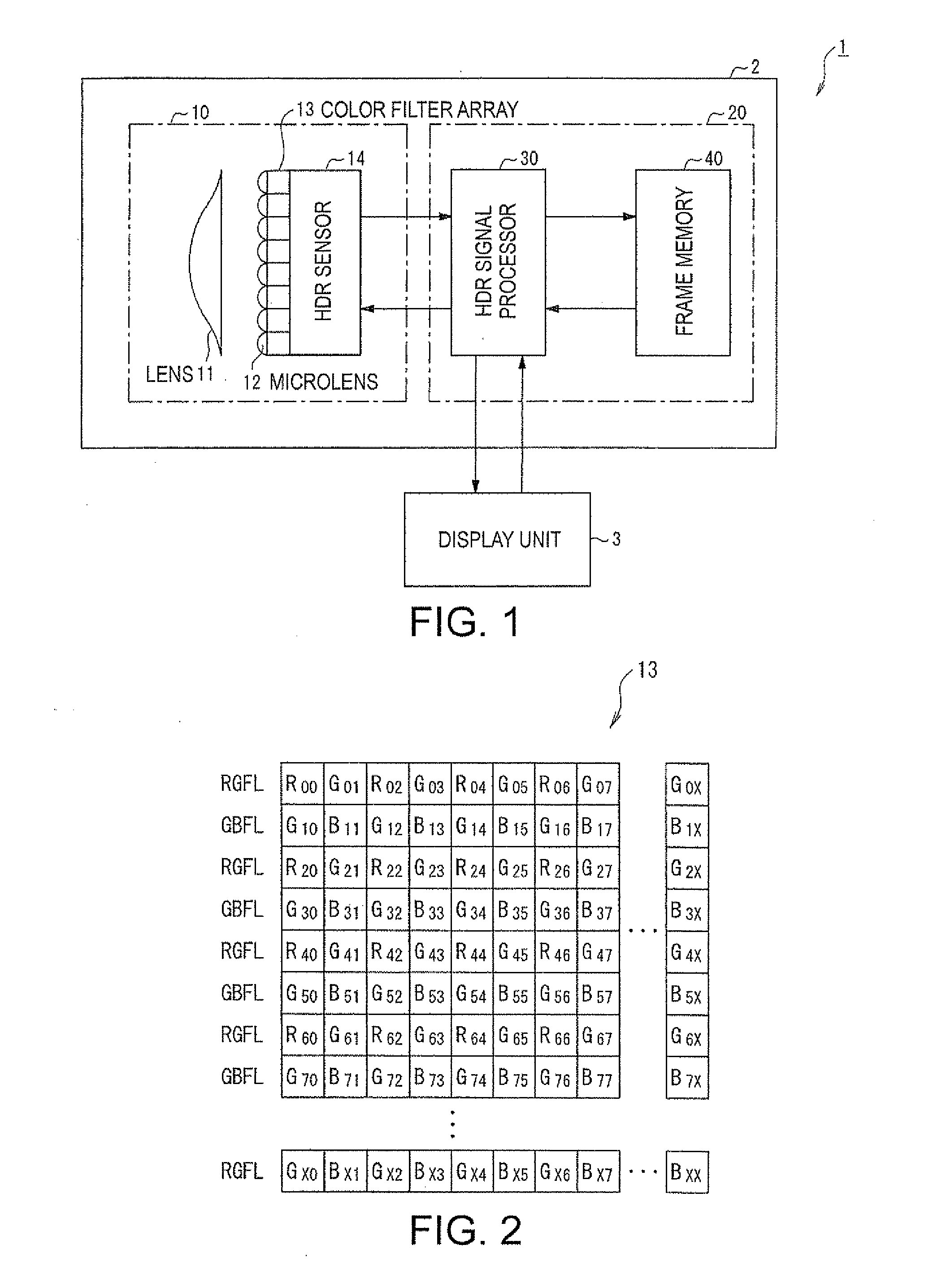
[0128]First, a configuration of an imaging system in accordance with the invention is described with reference to FIG. 1. FIG. 1 is a block diagram showing a configuration of an imaging system 1 in accordance with the invention.

[0129]As shown in FIG. 1, the imaging system 1 includes an imaging apparatus 2 and a display apparatus 3.

[0130]The imaging apparatus 2 includes an imaging device and an imaging control apparatus 20. The imaging control apparatus 20 includes an HDR signal processor 30 and a frame memory 40.

[0131]The imaging device 10 includes a lens 11, a microlens 12, a color filter array 13 and an HDR sensor 14.

[0132]The lens 11 collects light reflected by an object and guides the collected light to the microlens 12. Note that th...

second embodiment

[0244]Next, a second embodiment of the invention is described with reference to the drawings. FIG. 11 shows an imaging control apparatus, an imaging apparatus and an imaging control method in accordance with the second embodiment of the invention.

[0245]This embodiment is different from the first embodiment described above in that the HDR sensor 14 in the imaging device 10 in the first embodiment has a sensor cell array including two pixel groups having different sensitivities and outputs two pixel data SL and SH imaged by different pixels having different sensitivities. Here, let us assume that the sensitivity of a pixel that provides the pixel data SL is lower than that of a pixel that provides the pixel data SH.

[0246]Also, the configuration of the imaging control apparatus in accordance with this embodiment is different from that of the imaging control apparatus in accordance with the first embodiment described above in that the mainline processing of generating HDR image data fro...


PUM


Abstract

An imaging control apparatus includes an HDR signal processor and a frame memory. The HDR signal processor obtains pixel data S1 and S2 obtained by imaging with a very short exposure time T1 and a short exposure time T2 earlier than obtaining pixel data S3 obtained by imaging with a normal exposure time T3, generates a luminance image data by separating illumination light component from the pixel data S1 and S2, the generation of the luminance image data starting when the pixel data S2 is obtained, and generates a gain for tone mapping from the luminance image data. On the other hand, the HDR signal processor generates an HDR image data from the pixel data S1 to S3, the generation of the HDR image starting when the pixel data S3 is obtained, and performs tone mapping by multiplying this image data by the gain.

Description

[0001]The present application claims the priority of JP-2009-152604, filed on Jun. 26, 2009, which is incorporated by reference herein.TECHNICAL FIELD[0002]The present invention relates to an imaging apparatus and, more particularly, to an imaging control apparatus, an imaging apparatus, an imaging control method and the like suitable for reducing the amount of time taken for compressing the dynamic range of image data.BACKGROUND ART[0003]In one conventional technique, a plurality of versions of image data obtained by imaging with different lengths of exposure time are combined to generate dynamic-range-expanded image data (i.e., HDR image data). However, since HDR image data has a very wide dynamic range of, for example, 20-bit or the like, many of the existing display devices having a relatively narrow dynamic range of, for example, 8-bit or the like can not display HDR image data as it is. So, the dynamic range of HDR image data has needed to be converted to the dynamic range of ...

Claims


Application Information

Patent Timeline
IPC IPC(8): H04N5/235H04N9/74
CPCH04N5/35554H04N5/2355H04N23/741H04N25/583
Inventor KURANE, HARUHISAKOBAYASHI, MASANOBU
Owner SEIKO EPSON CORP
Why Eureka
Try Eureka