Fast Channel Switch Between Digital Television Channels

a digital television channel and channel switch technology, applied in the direction of color television with bandwidth reduction, selective content distribution, television systems, etc., can solve the problems of large software and/or system complexity, time it takes to switch from one channel to another channel, and large buffering requirements, so as to reduce the number of buffers.

Inactive Publication Date: 2010-12-30
ENTROPIC COMM INC
View PDF7 Cites 29 Cited by
  • Summary
  • Abstract
  • Description
  • Claims
  • Application Information

AI Technical Summary

Benefits of technology

[0005]It is an object of the invention to provide a method of outputting a digital video stream in which the number of buffers required is reduced without substantially comprising the channel switch time.
[0020]buffering the second transport stream to obtain a second buffered transport stream.In this embodiment the receiving of the second transport stream comprising the second plurality of time-multiplexed video channels effectively increases the total number of video channels to be selected from. Conventionally, transport streams are broadcasted (wireless or over physical networks) as an RF signal having a certain frequency band, for example having a width of 8 MHz. The RF signal is typically received by a tuner and demodulated into a stream of digital bits. The width of such frequency band typically determines the maximum amount of data that can be transmitted. Thus, in the digital domain the quantity of data (nr of bits) is fixed and thereby the number of bits per second of the transport stream. Each video channel that is comprised in the transport stream requires a certain amount of data. The higher the quality of the video channel the more data. Fixing the quality of the video channel thus determines the maximum amount of video channels that may be comprised in a transport stream. The number is typically somewhere between 2 and 8 for broadcast-quality TV channels. However, with a high-bandwidth stream, such as is possible with e.g. DVB-S2, and with very low-bitrate video channels, e.g. 300 kbit / second, it is possible to have more than 100 video channels in one transport stream. The buffering of the second transport stream, as is done for the first transport stream, thus features fast zapping between channels in different transport streams.
[0030]In an embodiment of the method in accordance with the invention the searching of the first buffered transport stream and / or the second buffered transport stream is started at the end of the respective buffered transport stream and carried out backwardly. The advantage of this embodiment is that when the first most recent-occurring GOP start is used then the latency with respect to real-time is kept minimal. It is also possible to find the most recent-occurring GOP start by starting at the beginning of the buffer and searching forward until the last GOP start. Searching backward until the first GOP start has the advantage that the searching is fastest.

Problems solved by technology

A well known disadvantage of digital television receivers compared with analogue television receivers is that the time it takes to switch from one channel to another channel is much longer in a digital television receiver.
A severe problem of the known method is that it requires quite a number of buffers, i.e. one buffer per digital video stream to which fast channel switch is required.
A large number of buffers also implies a larger software and / or system complexity for carrying out such method.

Method used


Image

  • Fast Channel Switch Between Digital Television Channels
  • Fast Channel Switch Between Digital Television Channels
  • Fast Channel Switch Between Digital Television Channels

Examples


first embodiment

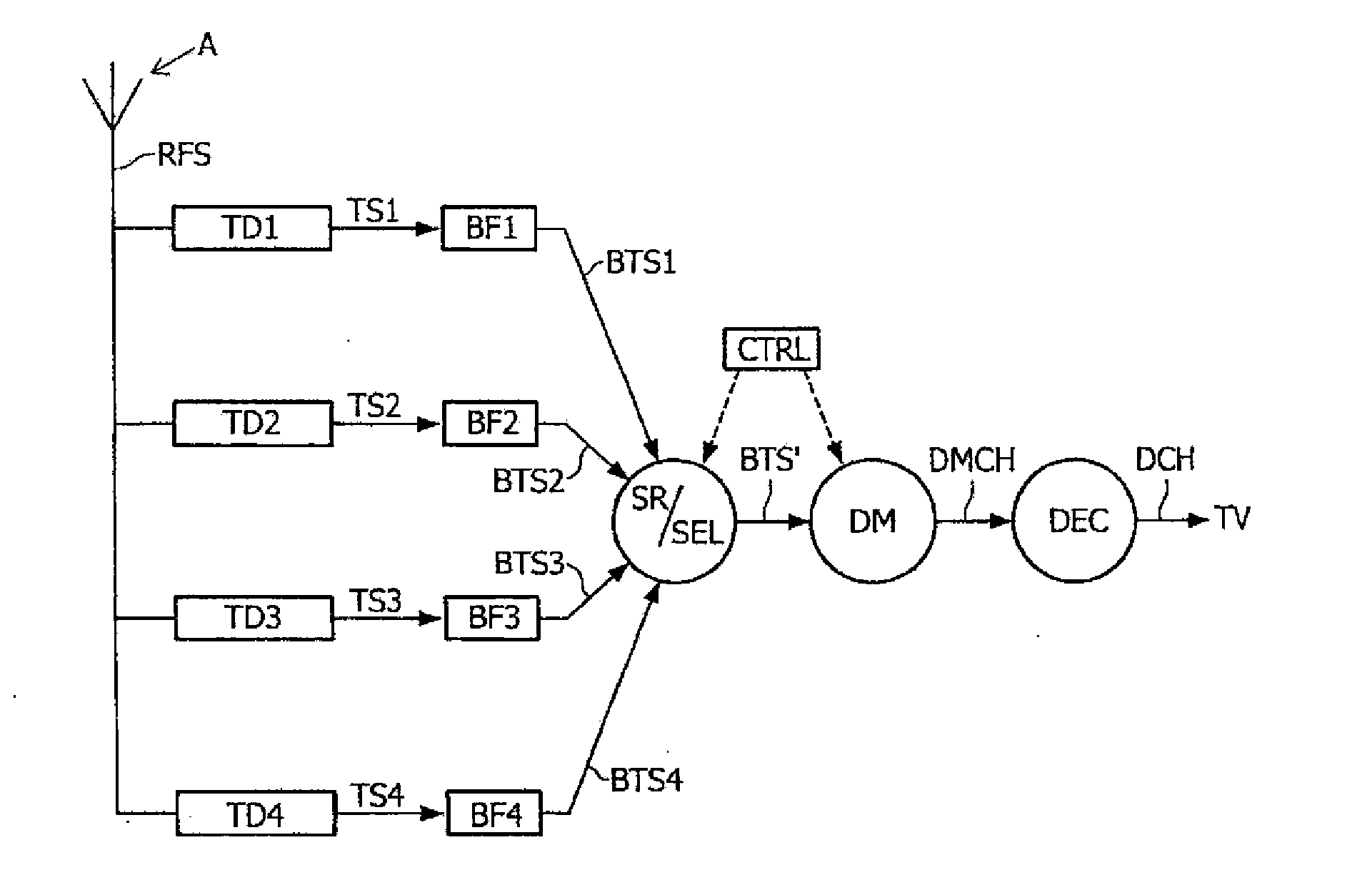
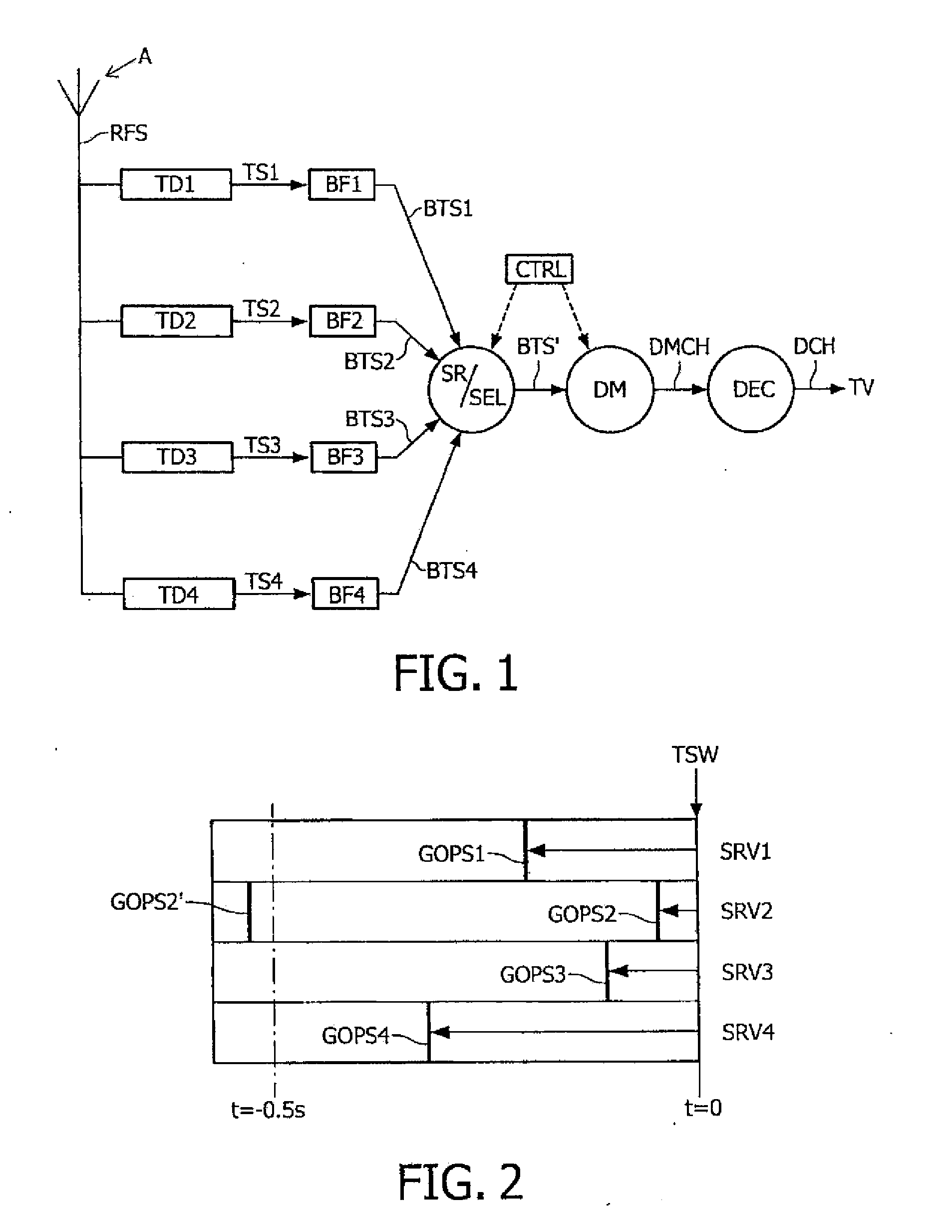
[0115]FIG. 1 shows a system in accordance with the invention. The system comprises an antenna A configured for receiving an RF modulated signal. In an alternative embodiment the antenna may be an antenna cable (which may be shared between different houses or buildings). The RF modulated signal is fed into four respective tuner / demodulator units TD1, TD2, TD3, TD4. This number of tuner / demodulator units is used throughout all examples in this description. However, the invention is not limited to a specific number of tuner / demodulator units. Any number equal to or larger than 1 is possible. In general more tuner / demodulator units features receiving more transport streams in parallel. For the invention this means that more channels benefit from fast-zapping feature between channels. Each tuner / demodulator unit is preferably tuned to a particular one of available frequency bands, each band comprising a plurality of channels or services in a single transport stream. Typically one such fr...

second embodiment

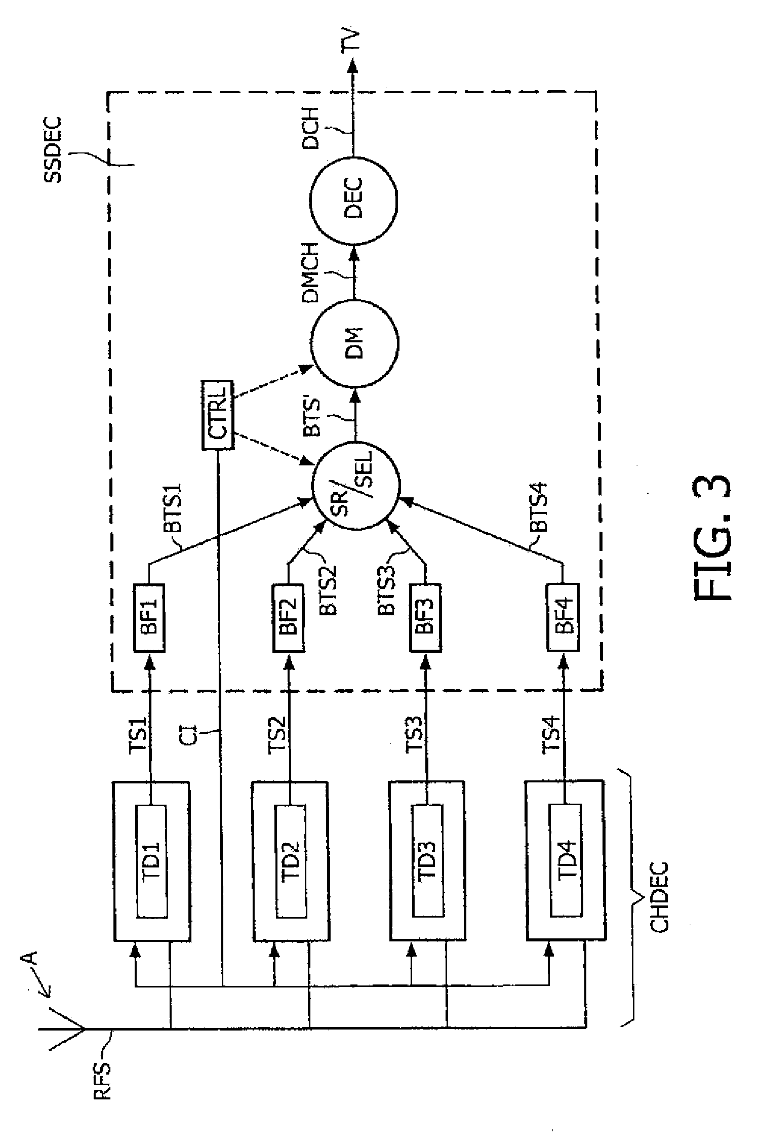
[0140]FIG. 3 shows a system in accordance with the invention. This figure will be discussed in as far as it differs from FIG. 1. A first difference is that a control signal CI (for example using an I2C interface) has been illustrated from the controller CTRL to the respective tuner / demodulator units TD1, TD2, TD3, TD4. The control interface / control signal CI from the controller to the tuner / demodulator units TD1, TD2, TD3, TD4 serves to tune in the respective tuners on a specific frequency band. After tuning in of the tuners no further control of the tuner / demodulator units is required. FIG. 3 further shows four channel decoders CHDEC that are coupled to a special source decoder SSDEC, each channel decoder comprising a respective one of the earlier mentioned tuner / demodulator units TD1, TD2, TD3, TD4. The channel decoders (i.e. tuner / demodulators) produce transport streams TS1, TS2, TS3, TS4. The buffering is done in the special source decoder SSDEC. To this end the special source d...

third embodiment

[0141]FIG. 4 shows a system in accordance with the invention. This figure will be discussed in as far as it differs from FIG. 3. FIG. 4 also shows four channel decoders that are coupled to a (less) special source decoder SSDEC′ without the buffers. However, in this embodiment the transport stream buffers BF1, BF2, BF3, BF4 are integrated in the channel decoders instead of the source decoder, which makes each respective combination TDB1, TDB2, TDB3, TDB4 of tuner / demodulator and transport stream buffer a special channel decoder SCHDEC. In this embodiment an additional command is added to the control interface CI (e.g. I2C bus) between source decoder SSDEC′ and channel decoder SCHDEC: the source decoder SSDEC′ can request the channel decoder SCHDEC to start streaming its currently received multiplex for a particular service (i.e. TV program). This service is preferably identified by the PIDs of its elementary streams. The source decoder SSDEC′ can maintain an up-to-date mapping from s...


PUM


Abstract

The invention relates to a method for outputting a first digital video stream (BTS′). The method comprises: i) receiving a first transport stream (TS1) comprising a first plurality of time-multiplexed video channels (SRV1, SRV2, SRV3, SRV4); ii) buffering the first transport stream (TS1) to obtain a first buffered transport stream (BTS1); iii) selecting a first specific one from the first plurality of time-multiplexed video channels to obtain a first selected video channel (SRV1); iv) searching the first buffered transport stream (BTS1) for a first start (GOPS1) of a first group of pictures of the first selected video channel (SRV1), and v) outputting the first buffered transport stream (BTS1) starting from the first start (GOPS1) of the first group of pictures to obtain the first digital video stream (BTS′). The invention further relates to a system for carrying out such method. The invention provides for very fast channel switching (zapping) due to the fact that the start of the group of pictures of the selected channel is available in the buffer almost instantly.

Description

FIELD OF THE INVENTION[0001]The invention relates to a method for outputting a first digital video stream which features fast switching to a further digital video stream. The invention further relates to a system for performing such method, and to a computer program product comprising instructions for causing a processor to perform such method.BACKGROUND OF THE INVENTION[0002]A well known disadvantage of digital television receivers compared with analogue television receivers is that the time it takes to switch from one channel to another channel is much longer in a digital television receiver. A tuner in a digital television receiver produces a transport stream that contains one or more television channels or services. One service is selected and then decoded. Decoding the video stream of a particular service can start at the beginning of a group-of-pictures. The time to wait for the beginning of a group-of-pictures is a significant part of the time it takes to switch from one chan...

Claims


Application Information

Patent Timeline
Patent Type & Authority Applications(United States)
IPC IPC(8): H04N7/08
CPCH04N21/4384H04N5/44
Inventor BRANDSMA, EWOUTDE WAAL, KLAAS
Owner ENTROPIC COMM INC
Why Eureka
Try Eureka