
High density fiber distribution hub

a fiber distribution hub and high-density technology, applied in the field of optical communication networks, can solve the problems of limiting the fiber distribution hub, the limitation of the minimum bending radius of the fiber in use and storage, and the conventional fiber distribution hub is too large to be easily assembled and/or disassembled, so as to achieve the effect of reducing the time for fiber entry and connection, and easy operation on si

Inactive Publication Date: 2010-12-30
3M INNOVATIVE PROPERTIES CO
View PDF9 Cites 76 Cited by
  • Summary
  • Abstract
  • Description
  • Claims
  • Application Information

AI Technical Summary

Benefits of technology

[0006]Thus, according to an aspect of the invention, a fiber distribution hub with multiple functions is provided, and the fiber distribution hub can also be separately used. In addition, the fiber distribution hub can be operated easily on site, so that the time for fiber entry and connection is reduced.
[0007]Further, the present invention provides a compact and modular fiber distribution hub.

Problems solved by technology

However, the intrinsic attributes of the fiber itself result in limitations to the fiber distribution hub.
For example, one of the most important limitations relates to the minimum bending radius of the fiber in use and storage.
However, conventional fiber distribution hubs are too large to be easily assembled and / or disassembled.
However, in the cassette, a connector can only be provided to connect fiber from the splitter and that entering inside, which can not provide hot melt splice or mechanical splicing.
Meanwhile, the folding cassette can only be used for existing tube entry application rather than cable entry application.

Method used


Image

  • High density fiber distribution hub
  • High density fiber distribution hub
  • High density fiber distribution hub

Examples


Embodiment Construction

[0031]The features of the present invention will become readily apparent with reference to accompanying drawings and the detailed description contained hereinafter. Like reference numerals refer to like elements throughout the specification.

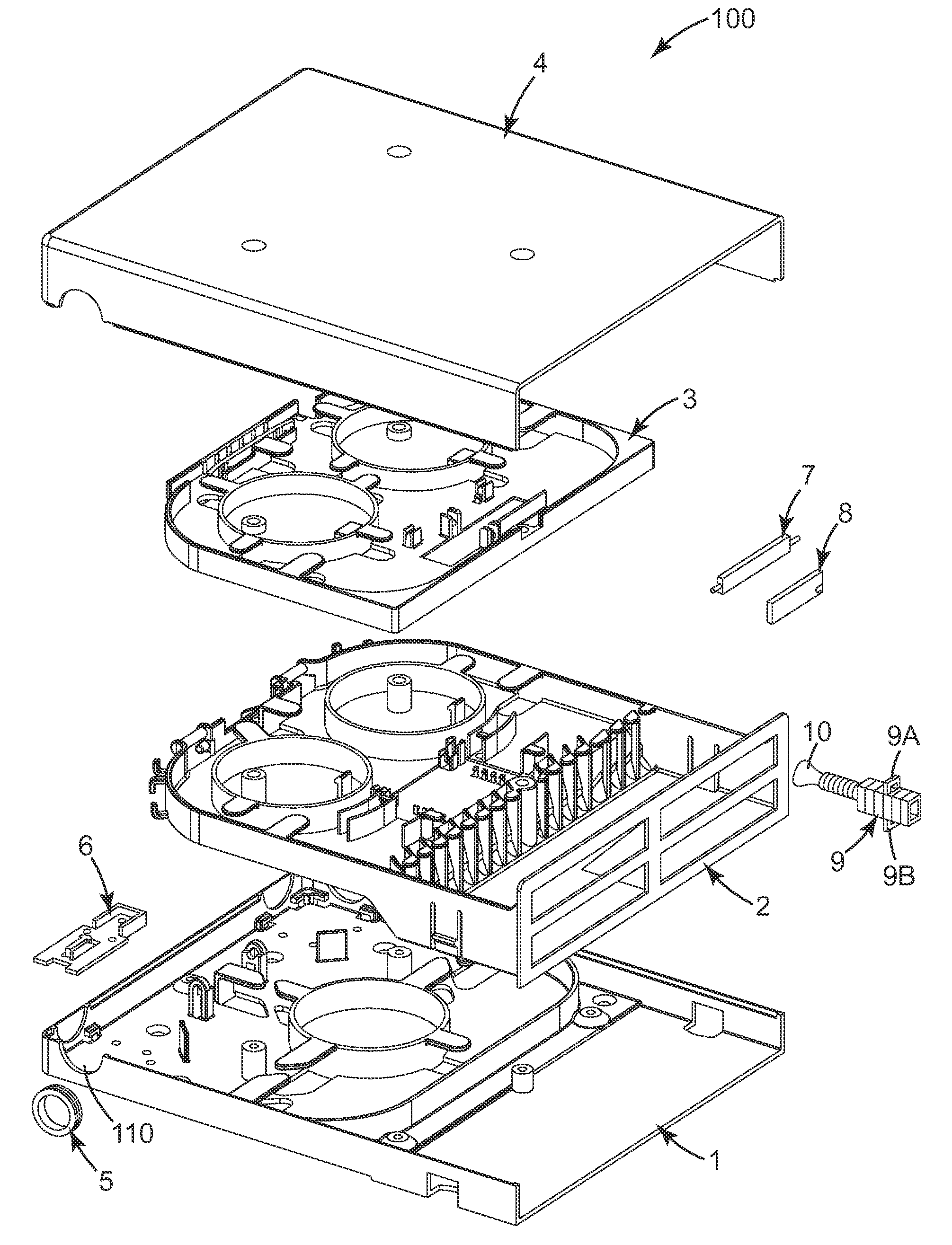
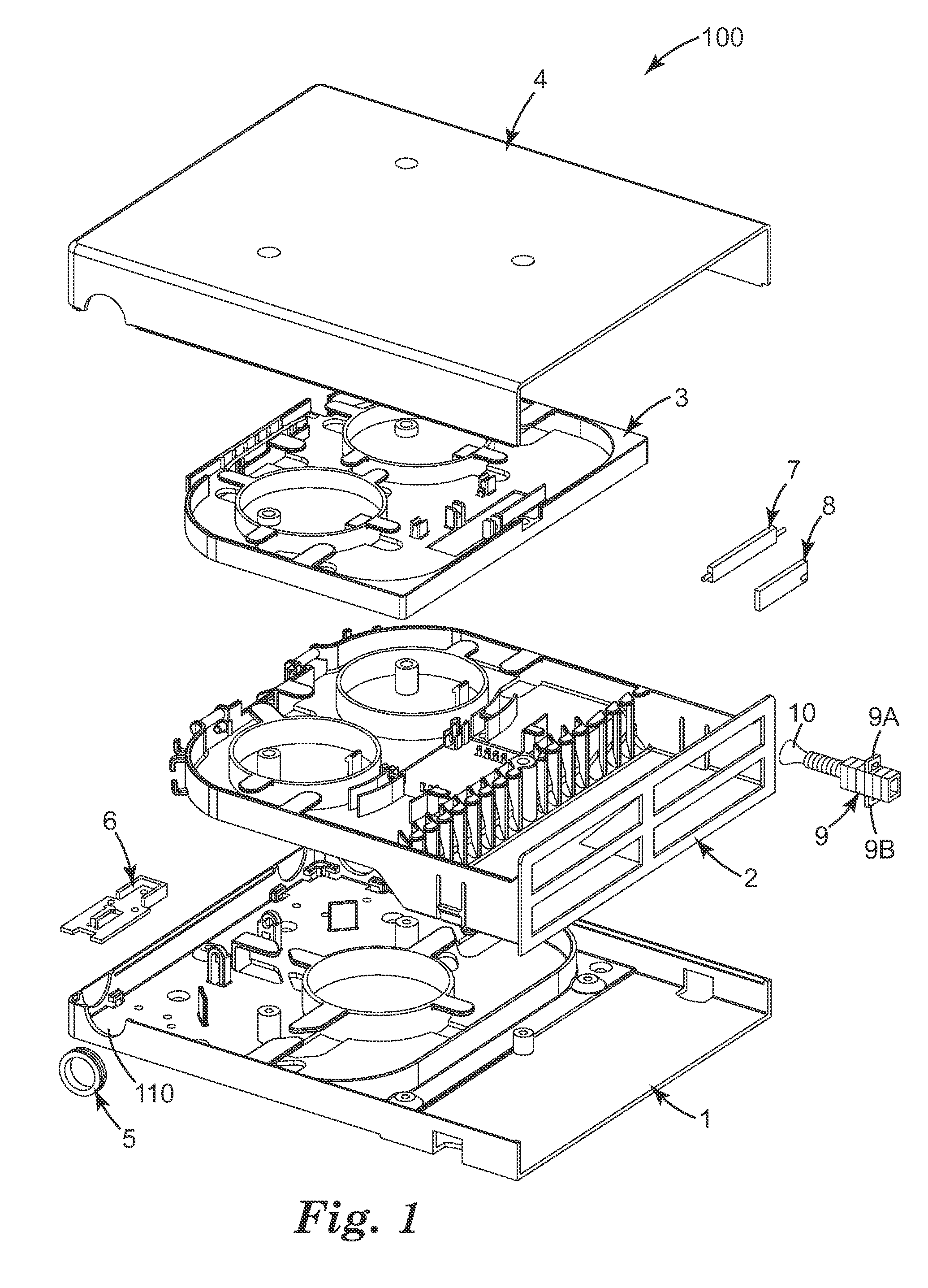
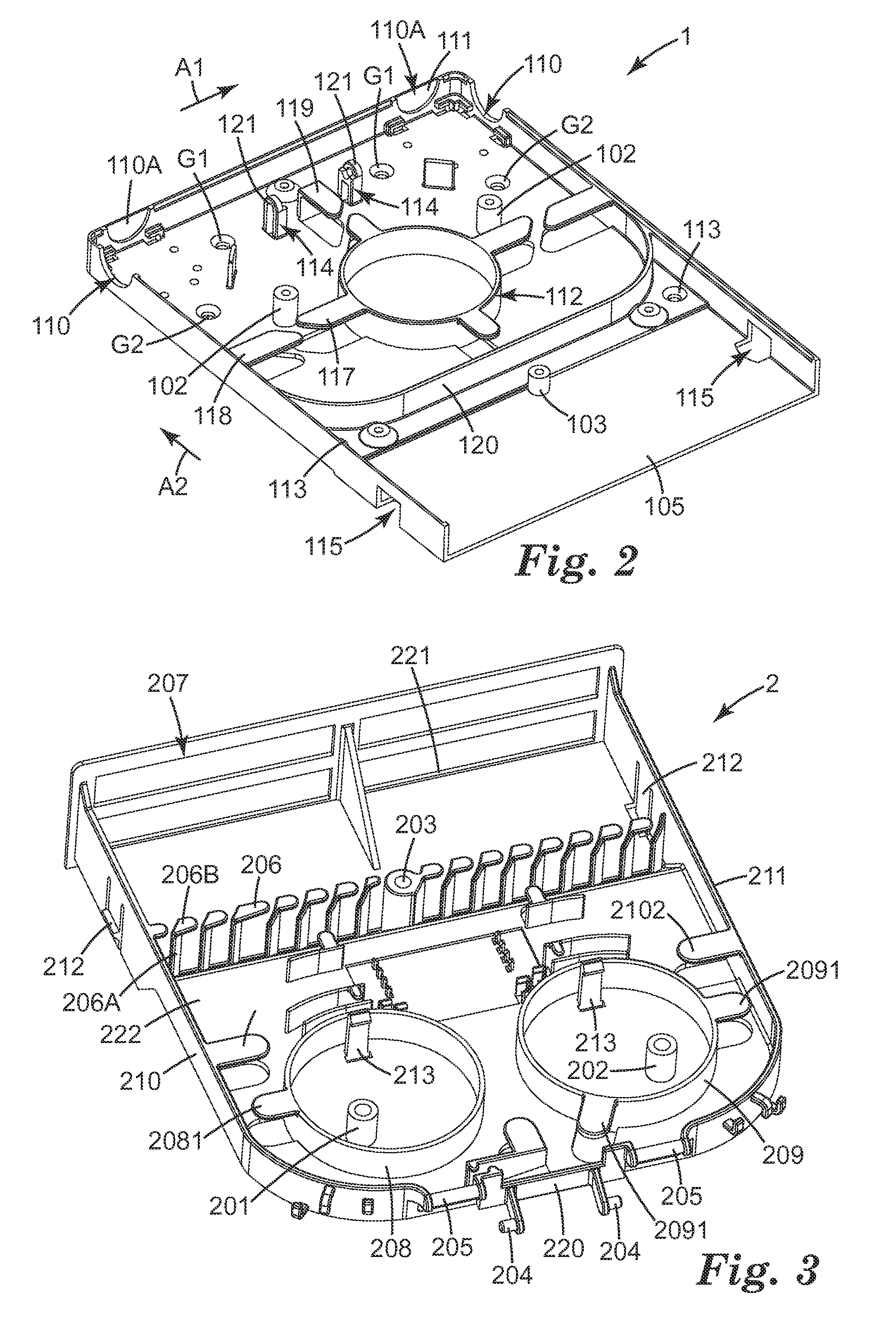
[0032]The detailed structure of the fiber distribution hub 100 will be described with reference to FIG. 1. Alternatively, this fiber distribution hub may be referred to a fiber distribution terminal or a fiber distribution unit. The fiber distribution hub 100 comprises a base case 1, a splitter case 2, a splice tray 3 and a cover 4. The splice tray 3 is pivotally connected to the splitter case 2. The cover 4 and the base case 1 are engaged to cover the splitter case 2 and the splice tray 3 when the base case 1 and cover 4 are joined together.

[0033]The fiber distribution hub 100 can not only be used for existing taut sheath cable but also for in-line cable. The taut sheath cable or in-line cable can enter into the fiber distribution hub 100 from a...


PUM


Abstract

The present invention relates to a fiber distribution hub. The fiber distribution hub comprises a base case comprising at least one port portion for introducing an optical cable, wherein the optical cable includes a first fiber; a splitter case releasably attached to the base case; a splice tray rotatably hinged to the splitter case; and a cover engagable with the base case to enclose the splitter case and the splice tray. The first fiber is connected to a second fiber in the splice tray, and the second fiber is connected with a splitter in the splitter case to separate the second fiber into a plurality of separate third fibers. Thus, the invention provides a compact and modular fiber distribution hub. In addition, the fiber distribution hub can join optical fibers by mechanical splices, fusion splices and fiber optic connectors in a single unit.

Description

TECHNICAL FIELD[0001]The present invention relates to optical communication network field, more specially, to a fiber distribution hub for fiber to home at floor building distribution level.TECHNICAL BACKGROUND[0002]Optical fiber is widely used in modern telecommunication field. Thus, a fiber distribution hub is an important product in an optical fiber communication network. The fiber distribution hub can provide an interface for a subscriber connected by patch cord between main cable and distribution cable. However, the intrinsic attributes of the fiber itself result in limitations to the fiber distribution hub. For example, one of the most important limitations relates to the minimum bending radius of the fiber in use and storage. If the fiber is bent with a radius smaller than the minimum radius of the fiber, the transmission performance of the fiber is reduced. For this reason, the fiber distribution hub should be designed carefully to ensure the minimum bend radius of the fiber...

Claims


Application Information

Patent Timeline
IPC IPC(8): G02B6/46
CPCG02B6/4454
Inventor ZHOU, JUNSHENGXU, ZHIYONGWANG, PINGBONVALLAT, PIERRE
Owner 3M INNOVATIVE PROPERTIES CO
Learn More