Torque sensor

a torque sensor and output technology, applied in the field of torque sensors, can solve problems such as errors in the output of torque sensors

Inactive Publication Date: 2011-01-06
KYB CORP
View PDF8 Cites 12 Cited by
  • Summary
  • Abstract
  • Description
  • Claims
  • Application Information

AI Technical Summary

Benefits of technology

[0006]However, in the conventional torque sensor, when the adhesive between the ring magnet and the back yoke constituting the magnetism generating portion peels away, a fixing position of the ring magnet shifts relative to the first shaft to which the back yoke is fixed, causing an error in the output of the torque sensor.

Problems solved by technology

However, in the conventional torque sensor, when the adhesive between the ring magnet and the back yoke constituting the magnetism generating portion peels away, a fixing position of the ring magnet shifts relative to the first shaft to which the back yoke is fixed, causing an error in the output of the torque sensor.

Method used


Image

  • Torque sensor
  • Torque sensor
  • Torque sensor

Examples


Embodiment Construction

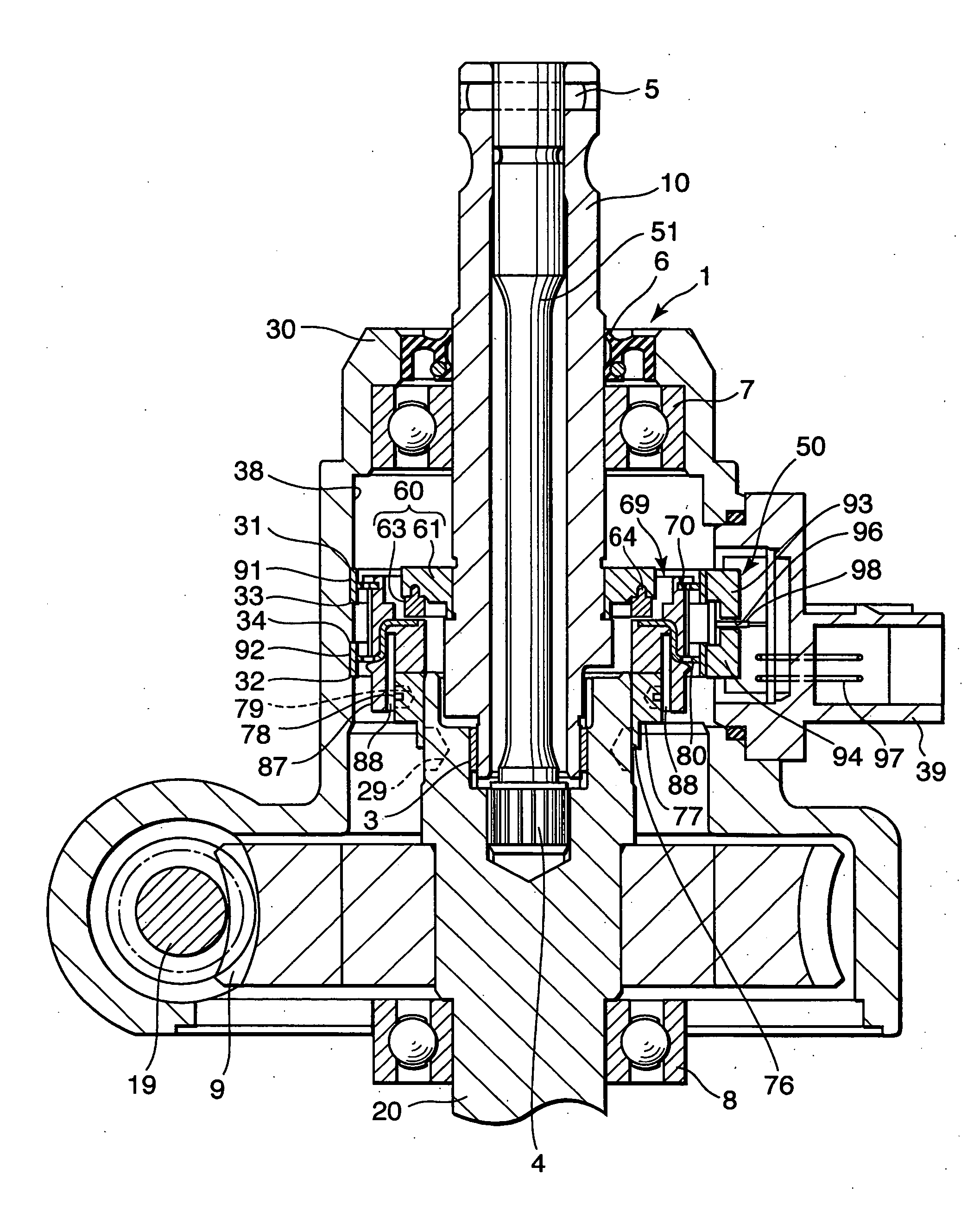
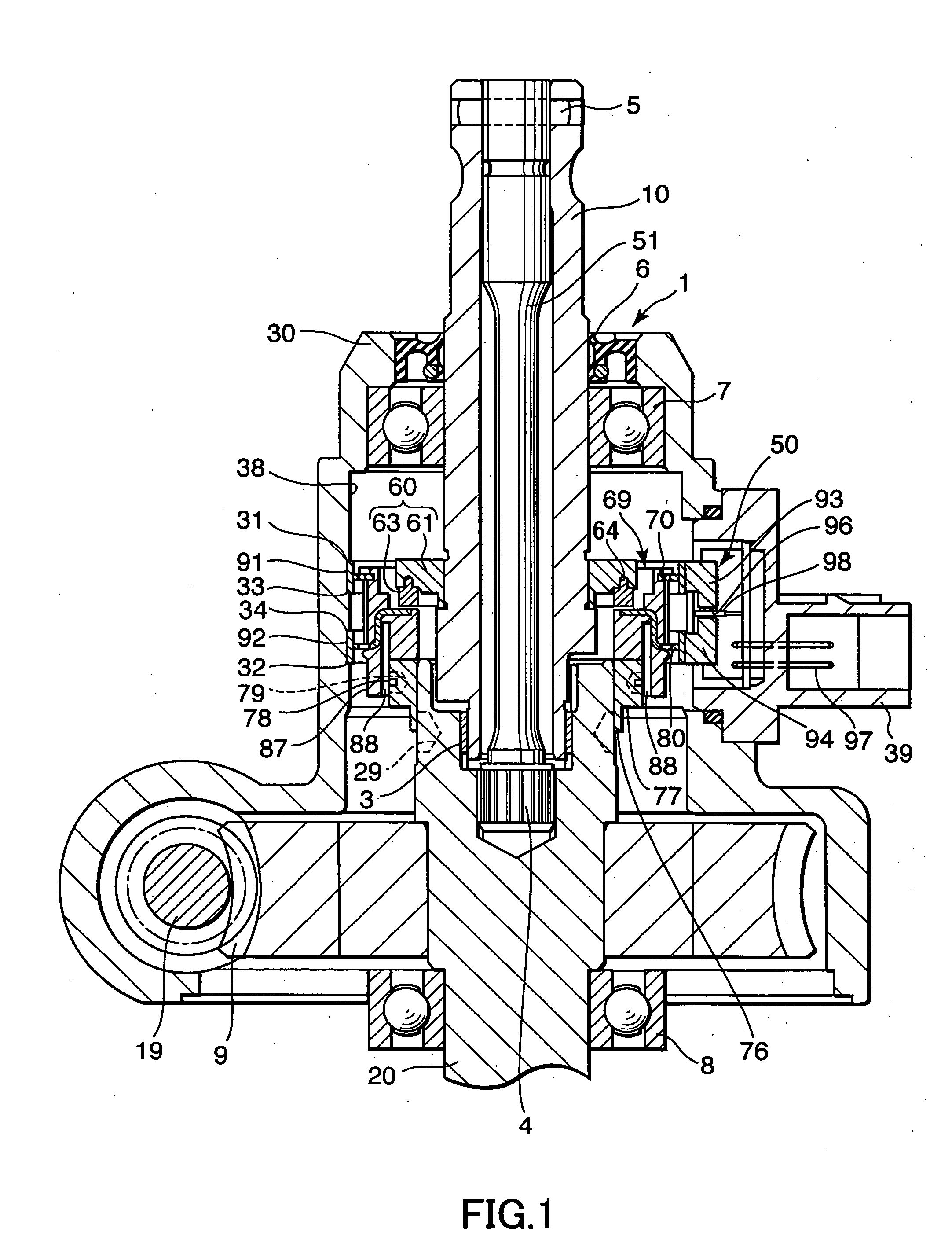
[0022]Referring to FIG. 1, a power steering device for a vehicle to which this invention is applied will be described.

[0023]In a power steering device 1, a first shaft 10 serving as an input shaft and a second shaft 20 serving as an output shaft are linked rotationally to a steering wheel such that when a rack shaft meshed to a pinion formed on a lower end of the second shaft 20 moves in an axial direction, a vehicle wheel is steered.

[0024]The power steering device 1 includes, as an assist mechanism for applying auxiliary steering torque, a worm wheel 9 coupled to the second shaft 20, a worm 19 meshed to the worm wheel 9, and an electric motor that drives the worm 19 to rotate. The power steering device 1 is formed such that the electric motor applies auxiliary steering torque to the second shaft 20.

[0025]The power steering device 1 includes a torque sensor 50 that detects the steering torque. The power steering device 1 is formed such that a controller controls an output of the ele...


PUM

PropertyMeasurementUnit
torqueaaaaaaaaaa
densityaaaaaaaaaa
magnetismaaaaaaaaaa

Abstract

In a torque sensor that detects torque acting on a torsion bar in accordance with the density of magnetic flux guided to a rotating magnetic circuit portion from a magnetism generating portion, the magnetism generating portion includes a back yoke that rotates together with a first shaft, a ring magnet joined to the back yoke, and an adhesive that is interposed between the back yoke and the ring magnet to join the two, and the adhesive includes a rotation-stopping projecting portion that engages with a rotation-stopping recess portion formed in the back yoke to function as a latch for stopping relative rotation between the back yoke and the ring magnet when an adhesion portion thereof adhered to the back yoke peels away.

Description

FIELD OF THE INVENTION[0001]This invention relates to a torque sensor that detects torque acting on a torsion bar in accordance with a density of magnetic flux derived from a magnet.BACKGROUND OF THE INVENTION[0002]Conventionally, a non-contact type sensor that detects steering torque acting on a rotating shaft via magnetic force is used as a torque sensor provided in a steering device of a vehicle.[0003]Torque sensors disclosed in JP2007-240496A and JP2007-292550A, published by the Japan Patent Office in 2007, respectively include a torsion bar housed rotatably in a housing, first and second shafts coupled to respective ends of the torsion bar, a multipolar magnet fixed to the first shaft as a magnetism generating portion, a multipolar yoke fixed to the second shaft as a rotating magnetic circuit portion, a fixed magnetic circuit portion fixed to the housing, and a magnetic sensor that detects the density of magnetic flux guided to the fixed magnetic circuit portion.[0004]When the ...

Claims


Application Information

Patent Timeline
Patent Type & Authority Applications(United States)
IPC IPC(8): G01L3/10
CPCG01L3/104G01L5/221
Inventor MAEHARA, HIDEO
Owner KYB CORP
Why Eureka
Try Eureka