Banknote identification apparatus

a technology for identification apparatus and banknotes, applied in paper-money testing devices, thin material processing, instruments, etc., can solve the problem of short lifetime of motors, and achieve the effect of reducing the load of motors, preventing motors from causing trouble, and preventing the life of motors

Inactive Publication Date: 2011-01-06
SANDEN CORP
View PDF5 Cites 1 Cited by
  • Summary
  • Abstract
  • Description
  • Claims
  • Application Information

AI Technical Summary

Benefits of technology

[0009]According to this invention, it is possible to reduce the load of the motor compared to a case in which being filled up of the storage with banknotes is judged by detecting the load of the motor. Therefore, it is possible to effectively prevent the motor from causing trouble and prevent its lifetime being shortened.

Problems solved by technology

Therefore, banknotes are continued to be mounted in the storage until the load of the motor becomes large, and it tends to cause a trouble and its lifetime tends to be short.

Method used


Image

  • Banknote identification apparatus
  • Banknote identification apparatus
  • Banknote identification apparatus

Examples


first embodiment

[0022]FIGS. 1 through 10 show the present invention.

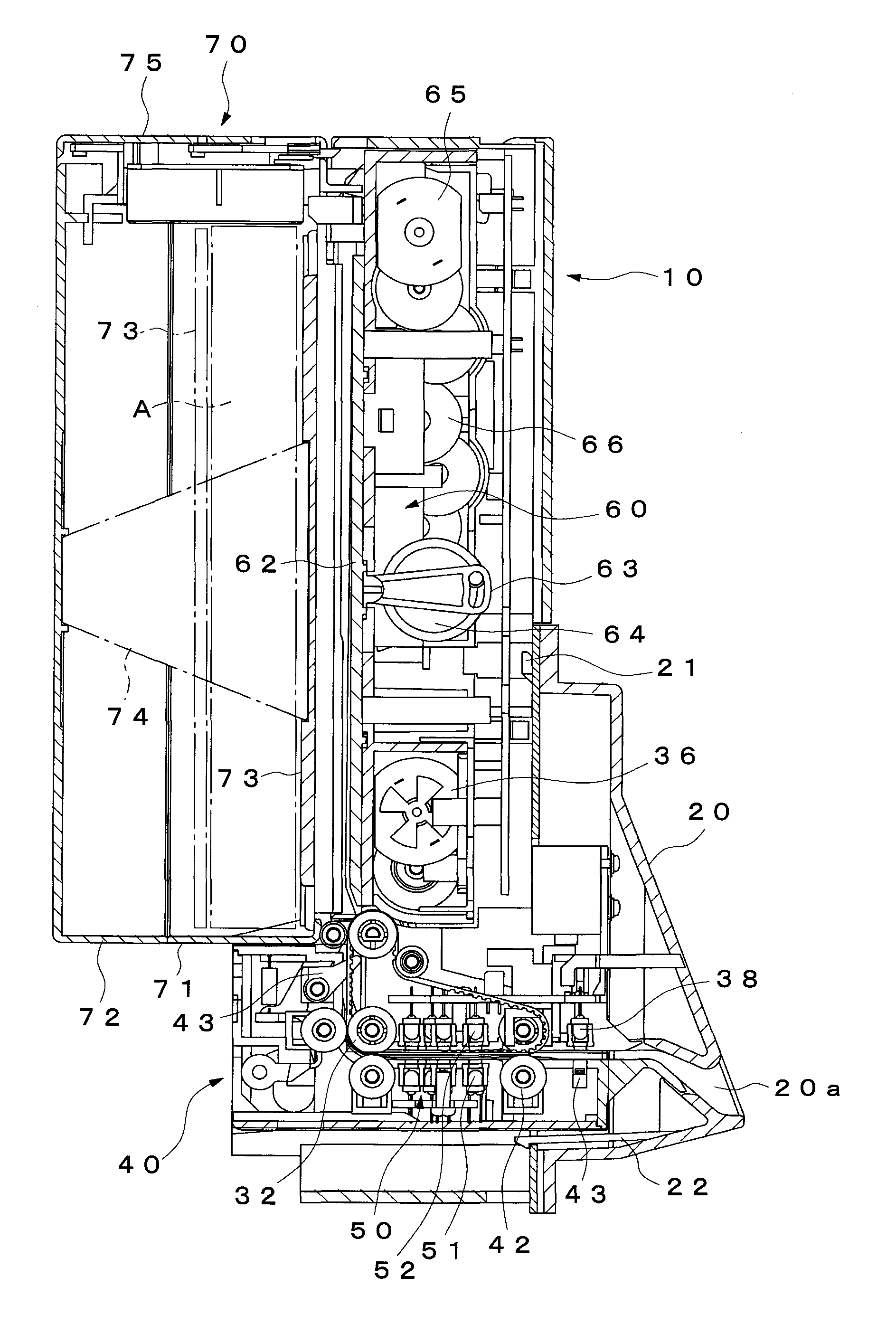
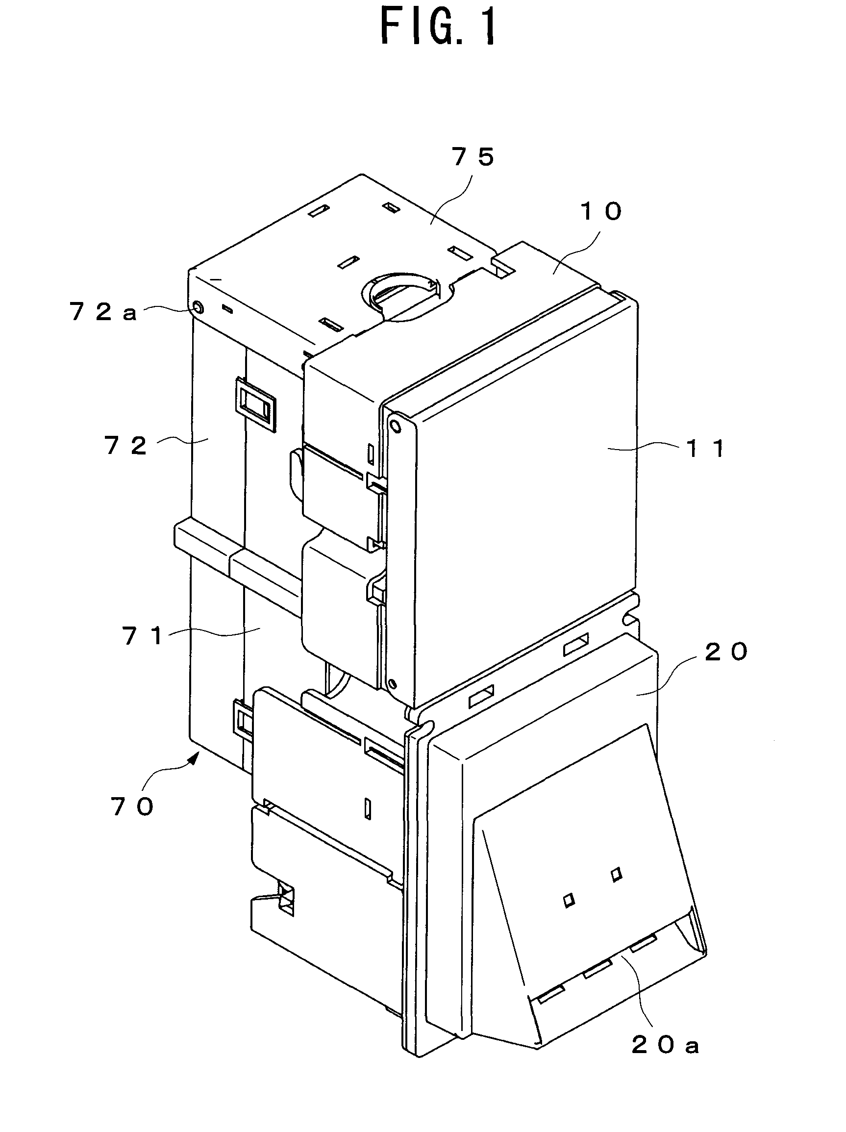
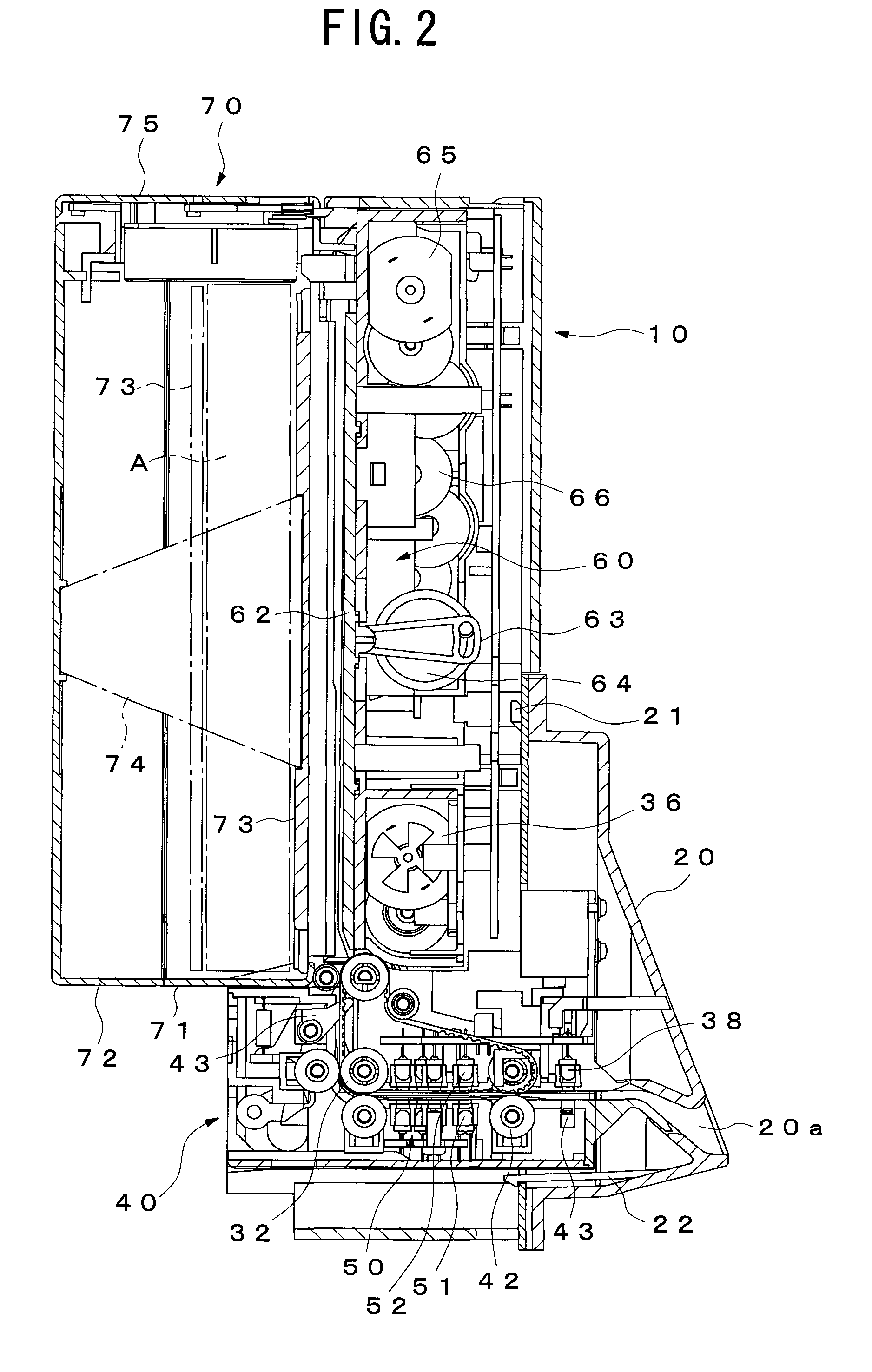
[0023]This banknote identification apparatus comprises a main body case 10 as an identification main body, a slot cover 20 attached at the front side of the main body case 10, a first and a second carry units 30 and 40 for carrying inserted banknotes A, an identification portion 50 for identifying the inserted banknotes A, a press unit 60 for pushing the banknote A which is carried to a destined position by each of the carry units 30 and 40 backward, a banknote storage unit 70 for storing the banknote A which is pushed by the press unit 60, and a controller 80 for controlling an operation of the banknote identification apparatus.

[0024]The main body case 10 is formed to be a box shape in which the rear side is opening, and an opening (not shown) covered by the slot cover 20 is provided at the lower front part of the main body case 10. Also, an open / close cover 11 for maintenance is provided at the upper front part of the main body c...


PUM


Abstract

An object of the present invention is to provide a banknote identification apparatus capable of reducing the load of a motor for driving a press member. When an amount of stored banknotes becomes larger than a predetermined amount, a banknote support plate moved to a predetermined position by reciprocal movement of a press plate is detected by an on/off operation of a detection switch, when a detected number thereof becomes larger than a predetermined number, banknotes are regulated not to be inserted. Therefore, it becomes possible to reduce the load of the motor of a press unit compared with the conventional apparatus which detects banknotes fully stored by an output load of the motor. Hence, it becomes possible to effectively prevent the motor from causing trouble and prevent its lifetime being shortened.

Description

TECHNICAL FIELD[0001]The present invention relates to a banknote identification apparatus which may be used with a vending machine to which banknotes are available.BACKGROUND ART[0002]Conventionally, a banknote identification apparatus having a identification portion for identifying the banknote inserted from a banknote slot, a carry structure for carrying the identified banknote to a predetermined position in an identification apparatus body, a banknote storage portion detachably provided in the identification apparatus body, a press plate moves between said predetermined position where the banknote is carried to by the carry structure and a predetermined position in the banknote storage portion, and the press plate pushes the banknote and storage the banknote in the banknote storage portion (see the patent document 1).[0003]The banknote identification apparatus detects output (voltage or current) corresponding load of a motor. Also, the number of banknotes becomes large and the de...

Claims


Application Information

Patent Timeline
Patent Type & Authority Applications(United States)
IPC IPC(8): G07F7/04
CPCB65H29/46B65H43/06B65H2511/30B65H2515/32B65H2701/1912G07D7/00G07D11/0021B65H2220/01G07D11/16
Inventor TADENUMA, ATSUHIROKATOU, HIROSHIKONDOU, TAKASHIIWAI, KOJINISHIO, JUNICHI
Owner SANDEN CORP
Why Eureka
Try Eureka