Vehicular torsion bar suspension device

a suspension device and torsion bar technology, applied in the direction of resilient suspensions, vehicle springs, interconnection systems, etc., can solve the problems of increasing the complexity of the drive system and steering system of the vehicle, increasing the cost of the vehicle, so as to prolong the life of the vehicle, reduce the horizontal vibration, and improve the effect of effective vibration of the running vehicl

Inactive Publication Date: 2011-01-06
SHIZUSN JINHUI SCI TECH & TRADING
View PDF46 Cites 11 Cited by
  • Summary
  • Abstract
  • Description
  • Claims
  • Application Information

AI Technical Summary

Benefits of technology

[0016]Owing to the connection mechanism provided between the front and rear torsion bar spring on the same side of the vehicle, specifically, owing to the gears provided at the ends of the two torsion bar springs, the linkage relationship can be established between the front and rear torsion bar spring on the same side, and as a result, improves the vibration effectively of a running vehicle on uneven roads. If the front wheels are given an upward force, the control arm of the suspension connected with the front wheels will transmit the force to the front torsion bar spring; at the moment, the front torsion bar spring will be distorted, and bring along the rear torsion bar spring to be twisted and distorted as well through the gear installed at its end and engaged with the end of the rear torsion bar spring, the rear torsion bar spring having an opposite distortion direction with the front torsion bar spring; that way, the front and rear wheels are given opposite force applied by the front and rear torsion bar spring, whereby the buffering is achieved, with about ½ of amplitude being offset, and accordingly the horizontal vibration is reduced. If the front wheels are given a downward force or the rear wheels are given an upward or downward force, the transmitting process of the force is the same as in the case where the front wheels are given an upward force; the action of the front and rear torsion bar spring can fulfill the buffering, with ½ of amplitude offset. When the front and rear wheels have the opposite vibration direction but the same amplitude of vibration, the torsion distortion of the front and rear torsion bar spring will be null, and the vibration of whole vehicle body is approximately null, which is the best status of the present suspension device because the shock absorption effect in this situation is the best and the vehicle can keep running horizontally. When four wheels are not on the same level, due to the counterforce of the front and rear torsion bar spring, the front and rear wheels get the same force, and accordingly the wheels that are in the diagonal positions get the same force, therefore the vehicle frame and body skeleton will not be acted upon by the torque force, and thus the life of the vehicle can be prolonged.

Problems solved by technology

However, this type of suspension structure has complicated structure, little carrying ability; and correspondingly, it makes the drive system and steering system of the vehicle get more complicated.
Even if the vibration direction of the front and rear wheels of the automobile is opposite, the impact the automobile gets will not be increased and the body will move in the manner that the front body goes up and the rear body goes down; moreover, when four wheels are not in a same surface or a pair of diagonal wheels bears a bigger force, the body and frame will get a certain amount of torque force; therefore, the current suspension structure still have the following pitfalls, e.g., elastic components are likely subject to be broken, the body and frame is likely subject to be distorted, and so on.
In addition, articles carried in vehicles might be damaged and the passengers will feel uncomfortable.

Method used


Image

  • Vehicular torsion bar suspension device
  • Vehicular torsion bar suspension device
  • Vehicular torsion bar suspension device

Examples


example i

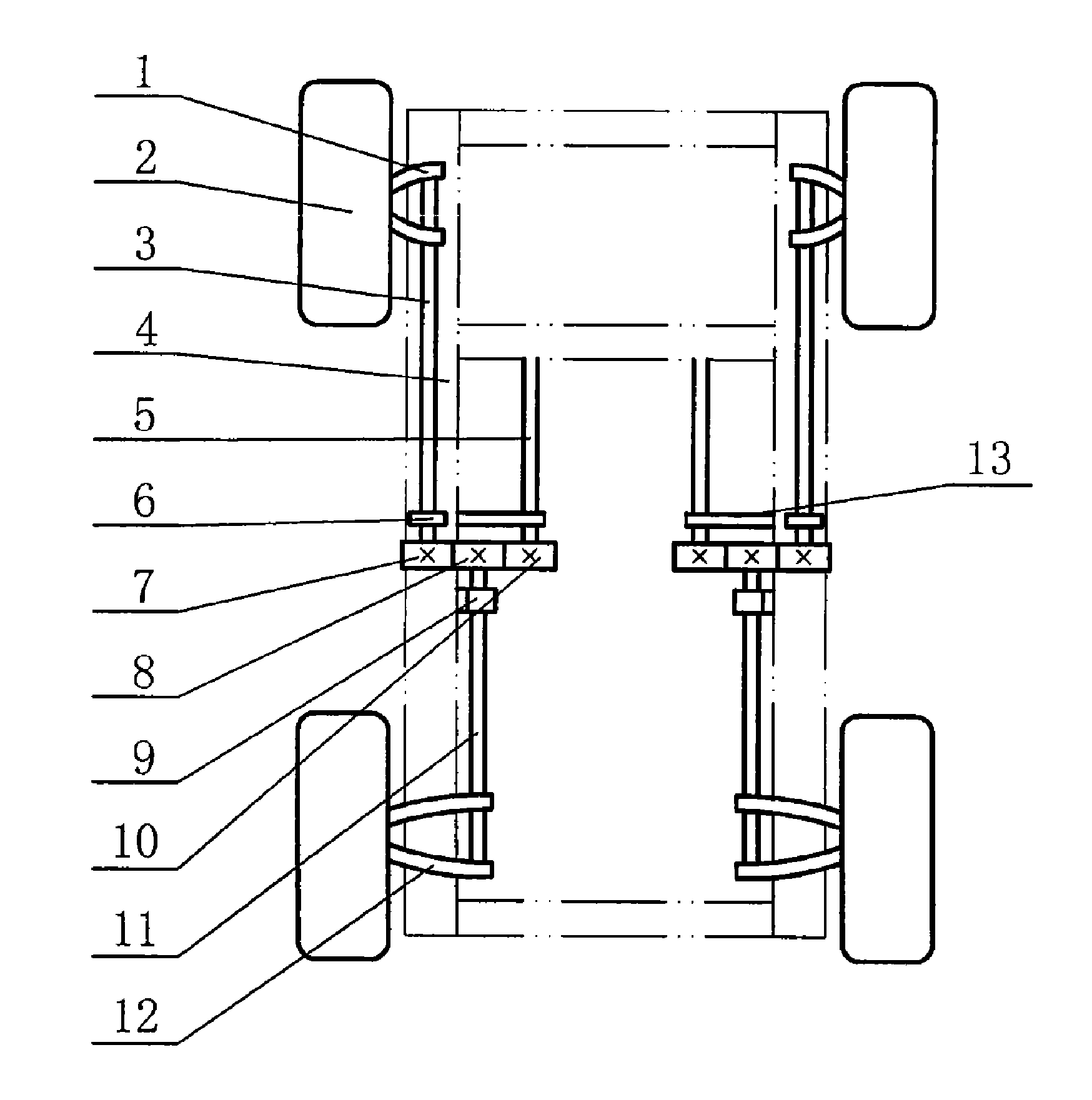
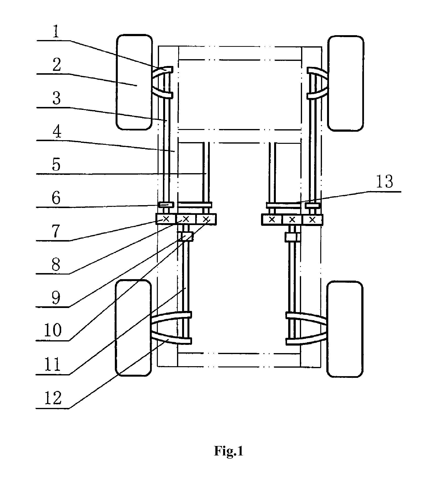
[0025]Referring to FIG. 1 the upper end of front torsion bar spring 3 is connected with the control arm 1 of the front suspension of the vehicle; the control arm is connected with the front wheel 2; the lower end of the rear torsion bar spring 11 is connected with the control arm 12 of the rear suspension; at the lower end of the front torsion bar spring and the upper end of the rear torsion bar spring on the both side, the left and the right, is installed with gears 7 and 8 respectively, wherein the a pair of gears on the same side is engaged with each other. The upper ends of two reset torsion bar springs 5 are connected fixedly with the vehicle frame 4, and the lower ends are installed with reset gears 10. The reset gear 10 is engaged with the gear 8 of the rear torsion bar spring on the same side. The three torsion bar springs on the same left side and the same right side said above, are connected with the vehicle frame 13 respectively through the bearing seat 6 of the front tor...

example ii

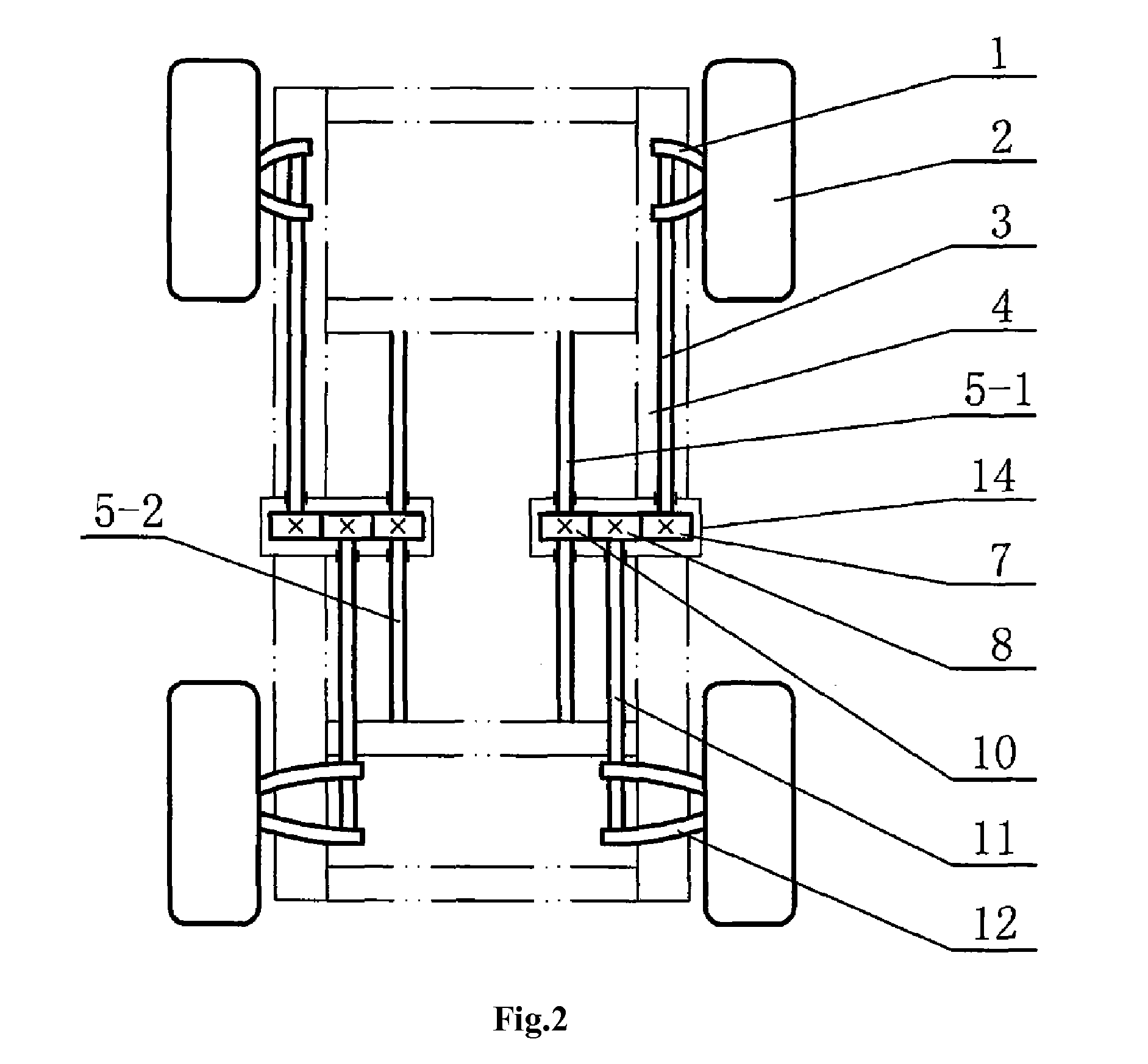
[0028]Based on Example I, to prevent the engaging gears from being polluted by various impurities, which will affect their life, as shown in FIG. 2, the three gears at the same side can be put in a gear box 14; by doing so, not only the working status is changed, but also when the gear box 14 is fixed to the vehicle frame 4, the three torsion bar springs at the same side can be positioned, so as to ensure that the three gears can be engaged with one another, and dispense with the three bearing seats. In addition, two extra reset torsion bar springs are installed to make the front and rear torsion bar springs restore rapidly after being distorted, which are front reset torsion bar spring 5-1 and rear reset torsion bar spring 5-2.

example iii

[0029]Based on Example II, when the suspension control arm is the double wishbone structure, as shown in FIG. 3 and FIG. 4, the upper end of the front torsion bar spring 3 of the left and right side is respectively mounted on the upper arm 1-1 of the control arm 1 of the front suspension of the left and right side; the lower end of the rear torsion bar spring 11 of the left and right side is respectively mounted on the upper arms of the control arm 12 of the rear suspension of the left and right side; the reset torsion bar spring 4 comprises of two front reset torsion bar springs 5-1 and two rear reset torsion bar springs 5-2, wherein the upper end of the front reset torsion bar spring 5-1 is connected with the lower arm 1-2 of the double wishbone of the control arm 1 of the front suspension, and the lower end of the rear reset torsion bar spring 5-2 is connected with the lower arm of the control arm 12 of the rear suspension, and the lower ends of the front reset torsion bar spring...


PUM


Abstract

A vehicular torsion bar suspension device, which comprises a front torsion bar spring and a rear torsion bar spring respectively installed at front and rear suspensions of the vehicle. The opposite ends of the front and rear torsion bar springs on the same side are connected mutually by a connection mechanism, and are connected with a vehicle frame through a positioning device. The connection mechanism is mounted between the front and rear torsion bar springs on the same side, so that a linkage relationship is established between the front and rear torsion bar springs. The device improves the vibration situation of the vehicle when driving the vehicle on an uneven ground, and prevents the vehicle frame and vehicle body skeleton from suffering torsional force. As a result, the usage life of the vehicle is prolonged.

Description

BACKGROUND OF THE PRESENT INVENTION[0001]1. Field of Invention[0002]The present invention pertains to a vehicle suspension device, especially, a vehicular torsion bar suspension device.[0003]2. Description of Related Arts[0004]Nowadays, there are two types of suspension system. One is non-independent suspension; the other is independent suspension. The axle of the independent suspension is divided into two sections. Each wheel is independently mounted through a spiral spring under the vehicle frame; as a result, when bumping happens to one wheel, the other wheel will not be affected, and thereby the vibrations of the vehicle body will be reduced drastically and accordingly improve the comfortability effectively; especially, when driving in a highway, the running stability will be increase as well. However, this type of suspension structure has complicated structure, little carrying ability; and correspondingly, it makes the drive system and steering system of the vehicle get more co...

Claims


Application Information

Patent Timeline
Patent Type & Authority Applications(United States)
IPC IPC(8): B60G11/20
CPCB60G11/18B60G11/181B60G21/045B60G2204/422B60G2202/132B60G2204/419B60G2200/144
Inventor LI, ZHIDONGLI, XIN
Owner SHIZUSN JINHUI SCI TECH & TRADING
Why Eureka
Try Eureka