Method and system for transferring information

Active Publication Date: 2011-01-06
ELSI TECHNOLOGIES OY
View PDF4 Cites 6 Cited by
  • Summary
  • Abstract
  • Description
  • Claims
  • Application Information

AI Technical Summary

Benefits of technology

[0023]The transmitter can influence the electromagnetic connection between the conductor component to be measured and t

Problems solved by technology

In this case identification does not succeed and position location measurement is only at the movement detection level.
In addition, the range of coverage of active systems is limited in indoor spaces by reflections and shadow areas.
The a

Method used


Image

  • Method and system for transferring information
  • Method and system for transferring information
  • Method and system for transferring information

Examples


Example

[0028]In the following the invention will be described in more detail with reference to some preferred embodiments presented as examples and to the attached drawings, wherein

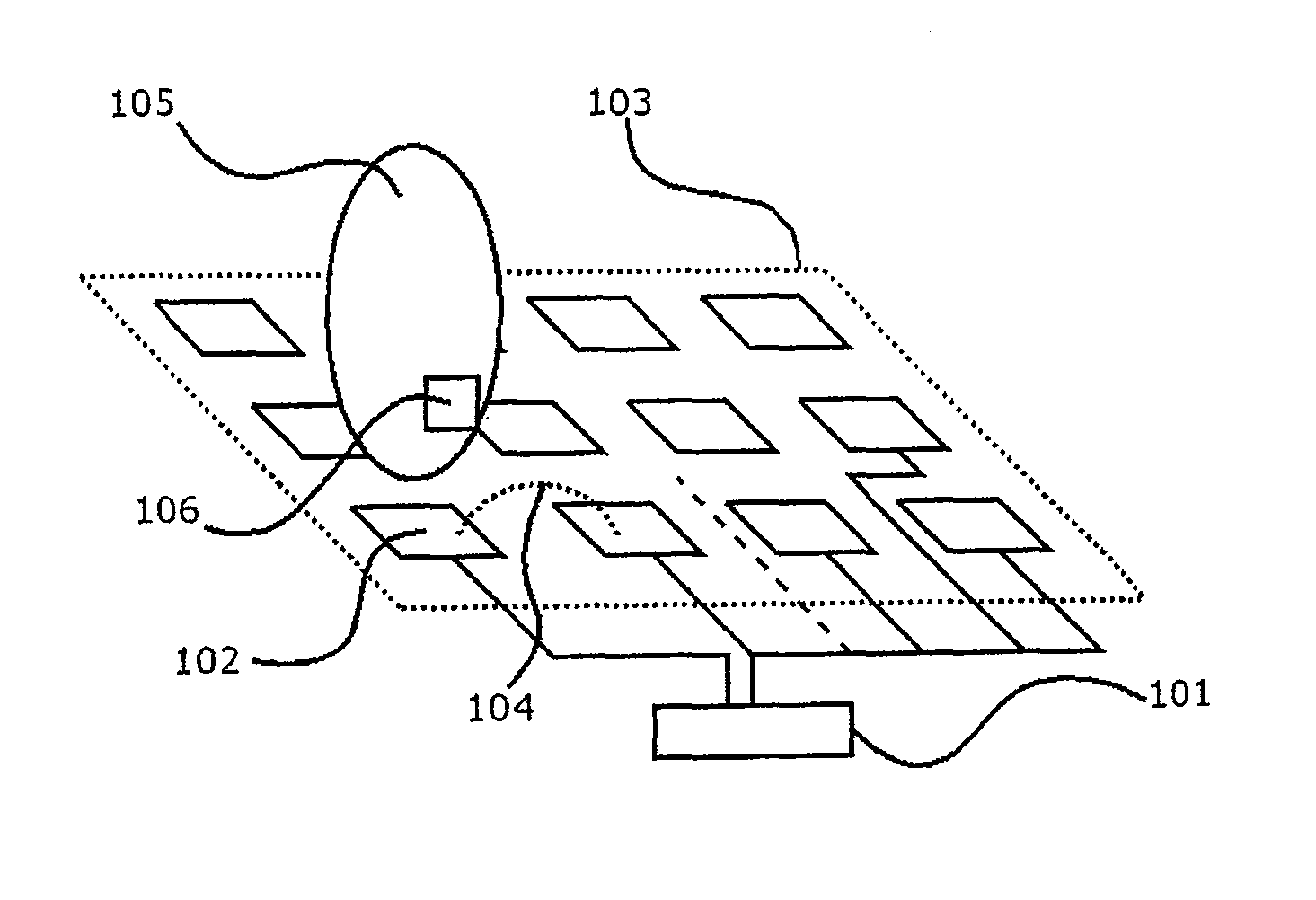
[0029]FIG. 1 presents one embodiment of the arrangement used in the invention,

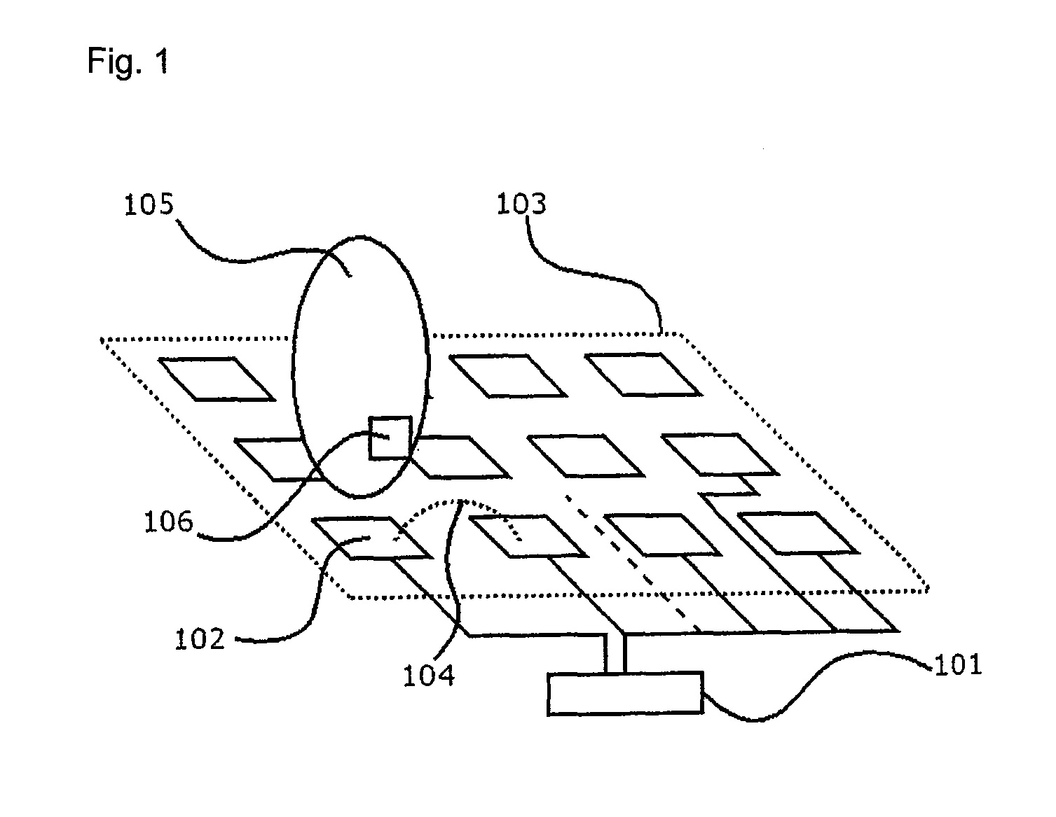
[0030]FIG. 2 presents one embodiment of the transmitter according to the invention and

[0031]FIG. 3 presents one exemplary application of the invention.

[0032]FIG. 1 presents a position location system and identification system, which is based on near-field measurement, according to one embodiment of the invention. The position location system (101) measures the electromagnetic connection of the conductor pattern (102), which is installed under the floor surface, to the conductor pattern group (103). In other words, the system (101) measures the impedance (104) of one conductor pattern (102) in relation to the whole conductor pattern group (103) with a spot frequency or with a variable frequency. The conductor patterns form a conductor m...


PUM


Abstract

The invention relates to a system for transferring information closely connected to an object. The system is characterized in that it comprises a conductor arrangement, which comprises a number of conductor components, that forms an electromagnetic field, as well as a transmitter associated with the object. The aforementioned transmitter is arranged to connect by means of an electromagnetic field to the conductor arrangement and also to modulate the measuring signal formed by means of the field.

Description

FIELD OF THE INVENTION[0001]The object of this invention is a method and a system, based on near-field measurement, for transferring information.STATE OF THE ART[0002]In prior-art indoor position location systems, which are based on a radio frequency, ultrasound frequency or infrared frequency measurement of delay or power, it is possible to locate and identify an object by means of a portable transponder or corresponding. Systems that operate by means of a transponder are in this context called active position location systems. Of these, only systems that operate at infrared frequencies also work without a transponder, i.e. as passive systems. In this case identification does not succeed and position location measurement is only at the movement detection level. In this case the changes in IR power between rough sectors are measured. Indoor position location systems that operate without a transponder are called in this context passive position location systems. These types of system...

Claims


Application Information

Patent Timeline
IPC IPC(8): G01R27/28
CPCG08B13/2402G01V3/12G01R29/08G08B21/22G01V3/104
Inventor RIMMINEN, HENRY
Owner ELSI TECHNOLOGIES OY
Why Eureka
Try Eureka