Image data processing apparatus and liquid ejection apparatus

a technology of image data and liquid ejection, which is applied in the direction of visual presentation, instruments, printing, etc., can solve the problems of requiring an enormous amount of calculation process and more visible preliminary dots

Active Publication Date: 2011-01-06
BROTHER KOGYO KK
View PDF7 Cites 3 Cited by
  • Summary
  • Abstract
  • Description
  • Claims
  • Application Information

AI Technical Summary

Benefits of technology

[0007]It is therefore an object of the present invention to provide an image data processing apparatus which makes preliminary dots formed on a recording medium in a preliminary ejection unnoticeable through a small amount of calculation, and to provide a liquid ejection apparatus including the image data processing apparatus.

Problems solved by technology

However, when an error diffusion processing is performed to image data, preliminary dots may be formed nearby image dots in an outer edge portion of an image, and these preliminary dots become more conspicuous.
Thus, an enormous amount of calculation process is required.

Method used


Image

  • Image data processing apparatus and liquid ejection apparatus
  • Image data processing apparatus and liquid ejection apparatus
  • Image data processing apparatus and liquid ejection apparatus

Examples


first embodiment

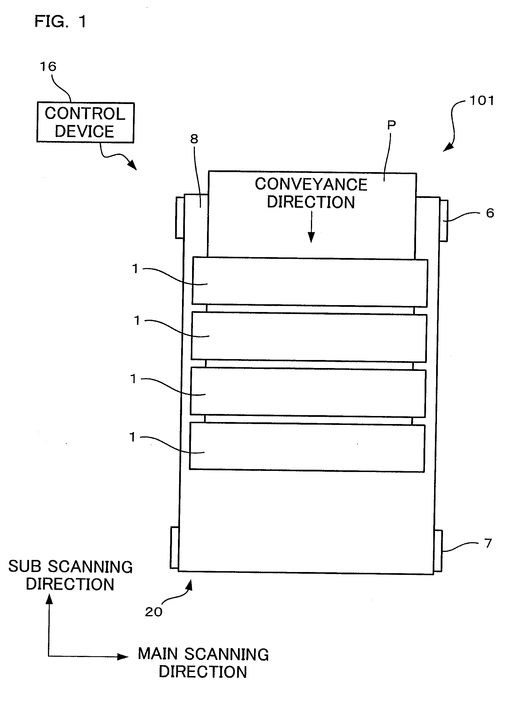
[0022]As shown in FIG. 1, an ink jet printer 101 of a first embodiment according to the present invention includes: a conveyance unit 20 which conveys a sheet P in a direction from the top to the bottom of FIG. 1; four ink jet heads 1 which respectively eject Magenta ink, Cyan ink, Yellow ink, and Black ink to the sheet P conveyed by the conveyance unit 20; and a control device 16 which controls the entire ink jet printer 101. In the present embodiment, a sub scanning direction refers to a direction parallel to a conveyance direction in which a sheet P is conveyed by the conveyance unit 20, and a main scanning direction refers to a direction which perpendicularly crosses the sub scanning direction along the horizontal plane.

[0023]The conveyance unit 20 has two belt rollers 6 and 7, and an endless conveyor belt 8 looped around the both rollers 6 and 7. The belt roller 7 is a drive roller which is rotated by a drive force from a not-shown conveyance motor. The belt roller 6 on the oth...

first modification

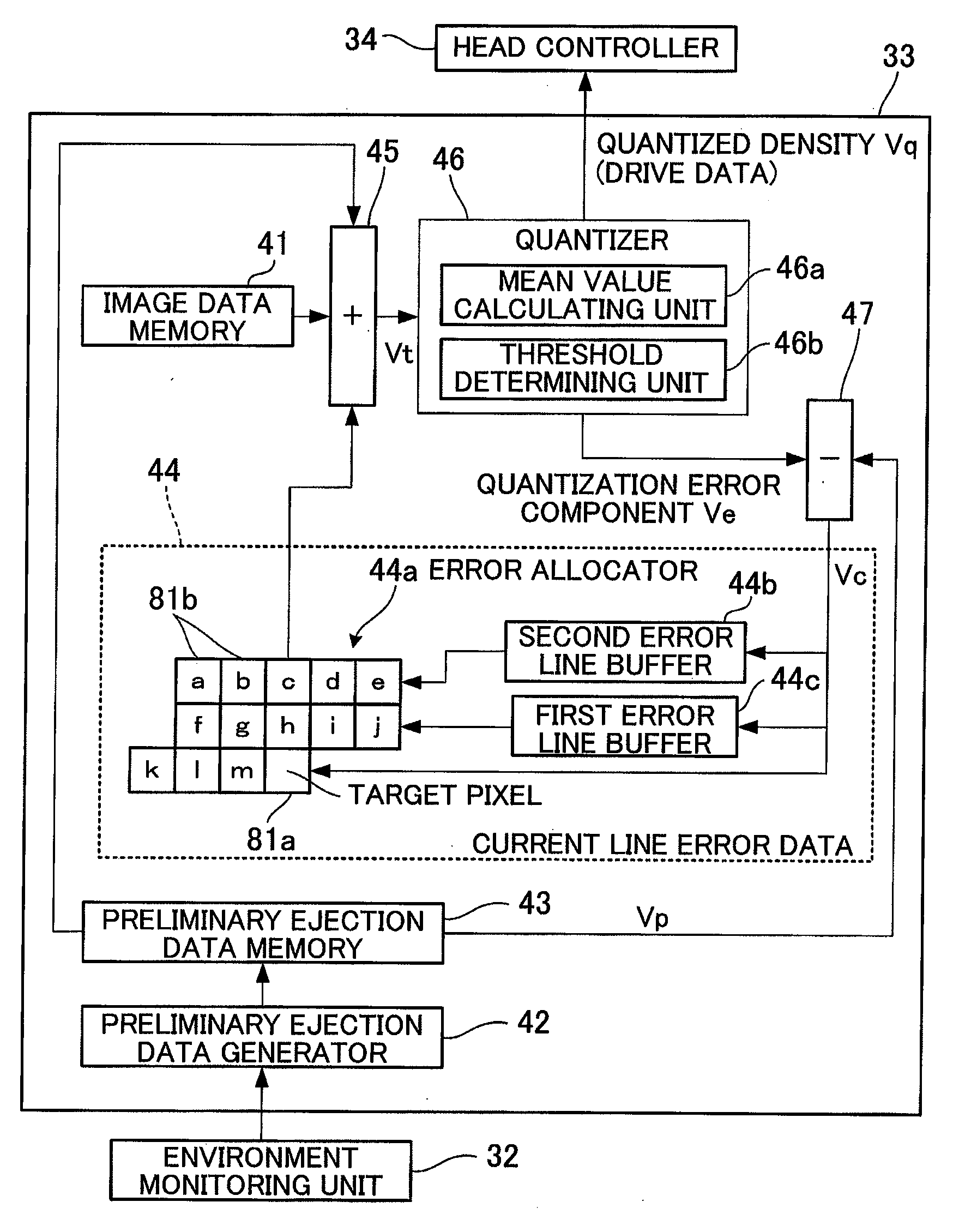
[0058]The above embodiment deals with a case where the quantizer 46 performs quantization through the Mean Density Preservation Method. However, the quantizer 46 may perform quantization through other methods. For example, quantization may be performed through the Mean Density Approximation Method. Specifically, the mean value calculating unit of the quantizer performs calculation of the mean value (mean density) of the densities related to thirteen pixels in total: i.e., a target pixel 81a and twelve quantized pixels 81c. This calculation is performed for each case where the density of the target pixel 81a is 0, 4, 8, and 12 respectively corresponding to the quantized densities of 0, 1, 2, and 3. It is preferable that the mean densities be calculated, after each density is weighed according to the weighing table shown in FIG. 10. Further, there is obtained absolute values of results of subtracting the total density Vt related to the target pixel 81a from the mean densities respecti...

second modification

[0059]In the above embodiment, the quantization error correction component Vc related to the target pixel 81a is error-diffused to the following thirteen non-quantized pixels 81b: three pixels k to m in the same pixel column as the target pixel 81a; five pixels f to j in the first adjacent pixel column; and five pixels a to e in the second adjacent pixel column. However, the range of error diffusion is not limited to this, and may be any given range, provided that the error diffusion is performed to non-quantized pixels. For example, as illustrated in FIG. 11A, the error diffusion may be performed to the following twelve non-quantized pixels 81b: two pixels a and b in the same pixel column as the target pixel 81a; five pixels c to g in an adjacent pixel column at downstream of the pixel column having the target pixel 81a relative to the conveyance direction; and five pixels pixel h to l in an adjacent pixel column at downstream of the pixel column having the pixels c to g relative t...


PUM


Abstract

Quantizing means generates a quantized density and a quantization error component for a target pixel in a plurality of pixels. A subtracter calculates, for the target pixel, a quantization error correction component by subtracting the density of the target pixel contained in preliminary ejection data from the quantization error component output from the quantizing means. An allocator allocates the quantization error correction component calculated by the subtracter to a plurality of the pixels around the target pixel. The quantizing means outputs the quantized density and the quantization error component of the target pixel by performing an addition using the density of the target pixel contained in the image data, the density of the target pixel contained in the preliminary ejection data, and the accumulated diffused error component assigned to the target pixel by the allocator when other pixels are quantized.

Description

CROSS REFERENCE TO RELATED APPLICATION[0001]The present application claims priority from Japanese Patent Application No. 2009-160052, which was filed on Jul. 6, 2009, the disclosure of which is herein incorporated by reference in its entirety.BACKGROUND OF THE INVENTION[0002]1 Field of the Invention[0003]The present invention relates to an image data processing apparatus related to a liquid ejection apparatus which records an image on a recording medium by ejecting a liquid from a plurality of ejection openings, and a liquid ejection apparatus including the image data processing apparatus.[0004]2 Description of the Related Art[0005]An ink jet head of an ink-jet printer has a plurality of nozzles for ejecting therefrom ink towards a recording medium such as a print sheet. In such an ink jet head, ink in each nozzle is sometimes thickened over time and thereby causes unstable ink ejection characteristics and ejection defects. A known approach to prevent this problem is a preliminary e...

Claims


Application Information

Patent Timeline
Patent Type & Authority Applications(United States)
IPC IPC(8): B41J29/38
CPCB41J2/16526H04N1/4052B41J29/38
Inventor SUZUKI, KATSUAKI
Owner BROTHER KOGYO KK
Why Eureka
Try Eureka