
Heater with improved airflow

a heater and airflow technology, applied in the field of fluid heaters, can solve the problems of many complicated and expensive manufacture, many are difficult and/or impossible to service and repair, and many are complex and expensive to manufactur

Inactive Publication Date: 2011-01-06
RUWACH DESIGN
View PDF23 Cites 5 Cited by
  • Summary
  • Abstract
  • Description
  • Claims
  • Application Information

AI Technical Summary

Benefits of technology

[0010]Objects of the invention include high performance, power and efficiency; a relatively small compact size; aesthetic appearance and one that can be easily modified for particular aesthetic considerations; ability to mount vertically or be floor mounted; easy to service; and modular in design.
[0011]An object is to provide interchangeable shells and shell designs, thus allowing optimal aesthetics and consumer selection.
[0012]An object is to provide modularity allowing components to be used in smaller and / or larger, higher-output designs.
[0017]An object of the present invention is to provide an aesthetic design that, in addition to being useful, is also novel, ornamental, and unobvious over known designs, including providing surprising and unexpected benefits of appearance and ornamental value.

Problems solved by technology

For example, many are complex and expensive to manufacture, and as a result overly expensive to consumers.
Many are difficult and / or impossible to service and repair.
Often they have poor air flow and / or do not provide a uniform heat in a good steady air flow.
Many have a poor appearance that detracts from a room's décor.
In addition to the above, known room heaters are not modular, and hence they are not easily modified to provide higher heat units.
Still further, they do not use common components, which drive up expense and complicate production.
In addition, the known room heaters are not flexibly designed.

Method used


Image

  • Heater with improved airflow
  • Heater with improved airflow
  • Heater with improved airflow

Examples


Embodiment Construction

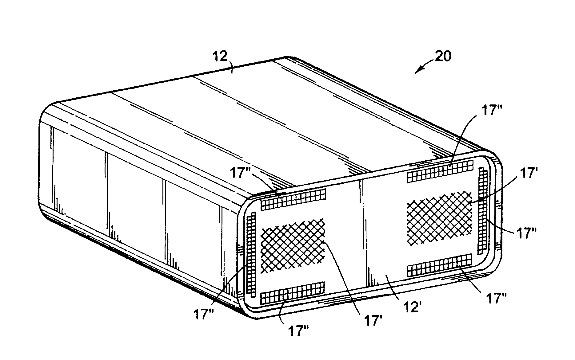
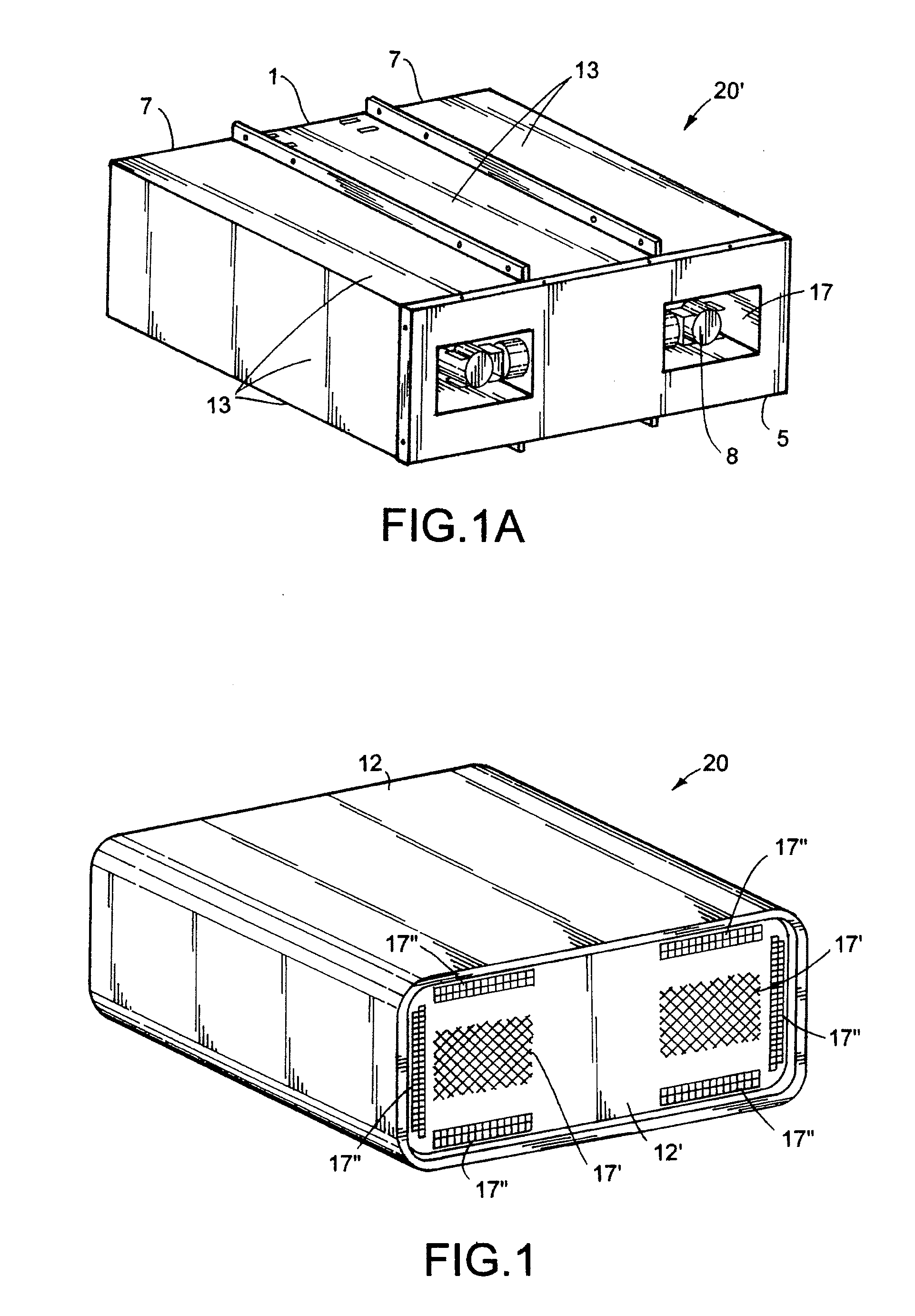
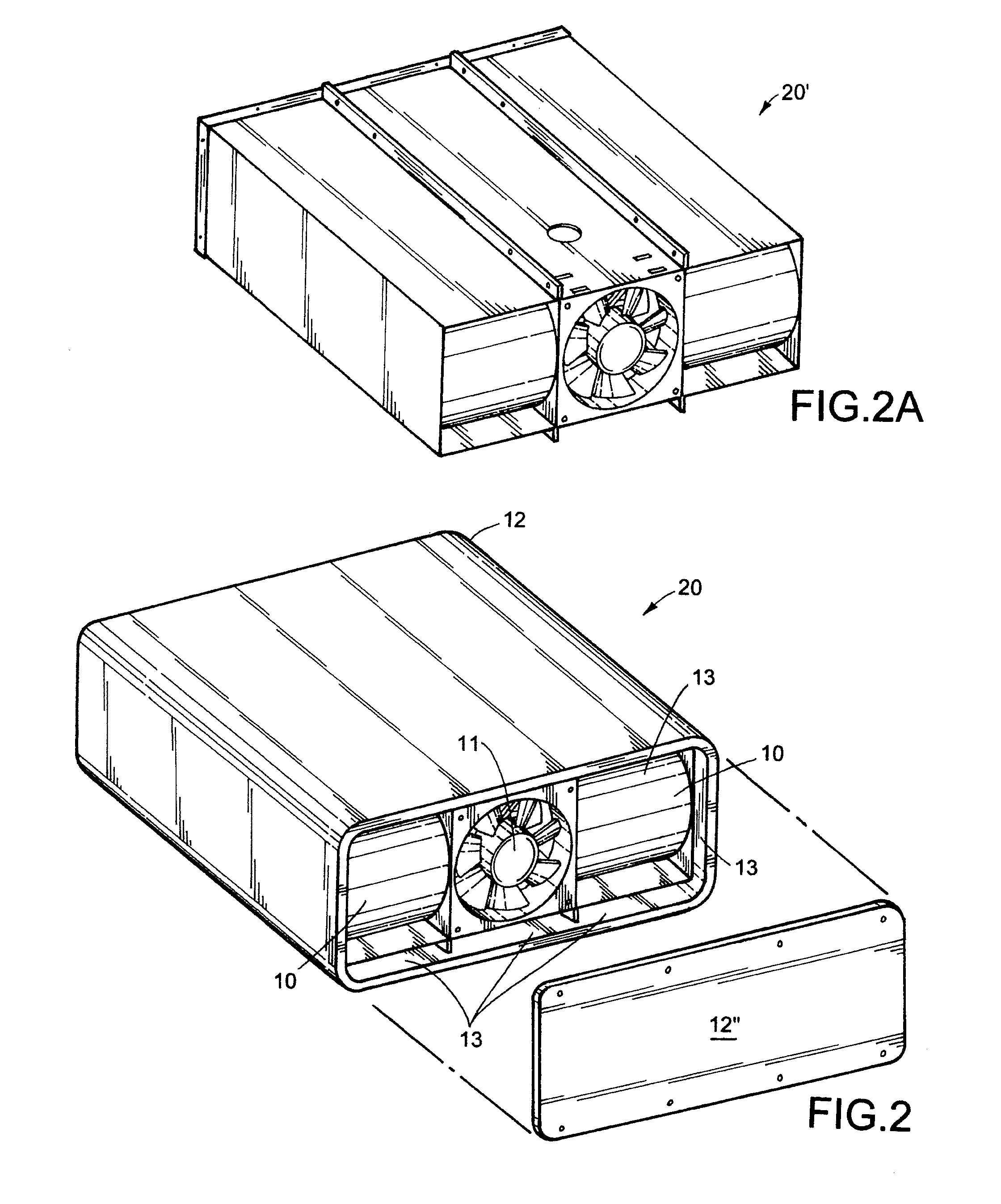
[0031]The illustrated room heater 20 (FIGS. 1-5, 9-10) (also called “space heater” or “heater apparatus”) is a side-by-side double-sided chamber, single-fan room heater embodying the present invention. FIGS. 1 and 2 show a housing assembly 20′ covered by an outer shell 12 and by face and back end covers 12′ and 12″, each having an aesthetic shape and aesthetic outer surface. The room heater 20 includes multiple wall-forming metal members 1, 3, 4, 5, 6, and 7 (FIG. 9) (also called “plates”) that when assembled form the housing assembly 20′ defining multiple back-and-forth tortuous paths for air. The paths (FIG. 10) include a first path 13′, along a first outermost preheat chamber(s) 13 (inside the shell 12 but outside the outer walls of the plates 3, 4 and 7 of the housing assembly 20′), a second path 14′ along second outer preheat chamber(s) 14 (centered and between plates 1, 1, 3, 4 of the housing assembly 20′), a third path 15′ along intermediate preheat chamber(s) 15 (between rig...


PUM


Abstract

The present room heater includes a housing supporting internal electric heat sources. The housing surrounds the heat sources with an interconnected serial series of chambers made from heat-conducting material. Air is motivated by an electric fan through the series of chambers to effect stepped uniform heating, as well as optimal heating as the air moves through preheat chambers and then closely past the heat sources to an outlet opening. The chambers are made using modular and relatively simply-made components that interfit to form the chambers, such that multiple configurations are possible, including stacked and laterally-adjacent versions. The modular components include a flat part, hat-shaped part, and U-shaped part that interfit to define a first elongated chamber and a second elongated chamber that wraps onto three sides of the first elongated chamber, the hat-shaped part having end-located notches to permit flow of air between the chambers.

Description

[0001]This application claims benefit under 35 USC section 119(e) of provisional application Ser. No. 61 / 270,091, filed Jul. 6, 2009, entitled QUARTZ INFRARED HEATER WITH IMPROVED AIRFLOW DESIGN, the entire contents of which are incorporated herein in their entirety.BACKGROUND[0002]The present invention relates to fluid heaters, and more particularly relates to room heaters, space heaters, and fluid heaters.[0003]Known room heaters are capable of improvement. For example, many are complex and expensive to manufacture, and as a result overly expensive to consumers. Many are difficult and / or impossible to service and repair. Often they have poor air flow and / or do not provide a uniform heat in a good steady air flow. Many have a poor appearance that detracts from a room's décor.[0004]In addition to the above, known room heaters are not modular, and hence they are not easily modified to provide higher heat units. Still further, they do not use common components, which drive up expense ...

Claims


Application Information

Patent Timeline
Patent Type & Authority Applications(United States)
IPC IPC(8): F24H3/02H05B3/02
CPCF24H3/0411F24H9/02F24H9/0073F24H9/0063
Inventor KRAPP, THOMAS E.GISH, DAVID G.
Owner RUWACH DESIGN
Learn More